Chrysler Sebring, Stratus sedan, Sebring Convertible. Manual - part 299


  Index      Chrysler     Chrysler Sebring, Stratus sedan, Sebring Convertible - service repair manual 2001-2007 year


Search            


Content   ..  297  298  299  300   ..


Chrysler Sebring, Stratus sedan, Sebring Convertible. Manual - part 299


CLUTCH

TABLE OF CONTENTS

page

page

CLUTCH

DESCRIPTION

. . . . . . . . . . . . . . . . . . . . . . . . . . 1

OPERATION

. . . . . . . . . . . . . . . . . . . . . . . . . . . . 2

DIAGNOSIS AND TESTING

DIAGNOSIS AND TESTING - CLUTCH

SYSTEM . . . . . . . . . . . . . . . . . . . . . . . . . . . . . 2

DIAGNOSIS AND TESTING - DRIVE PLATE

MISALIGNMENT . . . . . . . . . . . . . . . . . . . . . . . 4

DIAGNOSIS AND TESTING - CLUTCH

COVER AND DISC RUNOUT . . . . . . . . . . . . . . 4

DIAGNOSIS AND TESTING - CLUTCH

CHATTER COMPLAINTS . . . . . . . . . . . . . . . . . 5

DIAGNOSIS AND TESTING - CLASH-INTO-

REVERSE COMPLAINTS . . . . . . . . . . . . . . . . . 5

SPECIFICATIONS

CLUTCH

. . . . . . . . . . . . . . . . . . . . . . . . . . . . . 5

SPECIAL TOOLS

. . . . . . . . . . . . . . . . . . . . . . . . 6

CLUTCH PEDAL

REMOVAL

. . . . . . . . . . . . . . . . . . . . . . . . . . . . . 6

INSTALLATION

. . . . . . . . . . . . . . . . . . . . . . . . . . 6

CLUTCH PEDAL INTERLOCK SWITCH

DIAGNOSIS AND TESTING - CLUTCH PEDAL

INTERLOCK SWITCH

. . . . . . . . . . . . . . . . . . . 7

REMOVAL

. . . . . . . . . . . . . . . . . . . . . . . . . . . . . 8

INSTALLATION

. . . . . . . . . . . . . . . . . . . . . . . . . . 8

CLUTCH RELEASE BEARING AND LEVER

DESCRIPTION

. . . . . . . . . . . . . . . . . . . . . . . . . . 8

OPERATION

. . . . . . . . . . . . . . . . . . . . . . . . . . . . 8

REMOVAL

. . . . . . . . . . . . . . . . . . . . . . . . . . . . . 9

INSTALLATION

. . . . . . . . . . . . . . . . . . . . . . . . . . 9

CLUTCH RELEASE CABLE

DESCRIPTION

. . . . . . . . . . . . . . . . . . . . . . . . . 10

REMOVAL

. . . . . . . . . . . . . . . . . . . . . . . . . . . . . 10

INSTALLATION

. . . . . . . . . . . . . . . . . . . . . . . . . 10

MODULAR CLUTCH

DESCRIPTION

. . . . . . . . . . . . . . . . . . . . . . . . . 11

REMOVAL

. . . . . . . . . . . . . . . . . . . . . . . . . . . . . 11

INSTALLATION

. . . . . . . . . . . . . . . . . . . . . . . . . 11

CLUTCH

DESCRIPTION

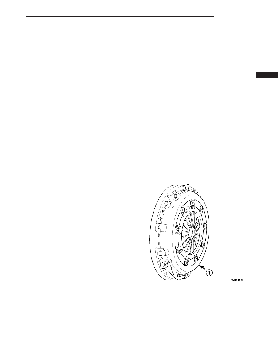
Manual transaxle equipped models utilize a modu-

lar clutch assembly. The clutch system consists of a
modular clutch assembly (Fig. 1), a sleeve type
release bearing, a self adjusting clutch cable, and a
clutch pedal that is part of a brake/clutch pedal
bracket assembly.

The modular clutch assembly consists of a single,

dry-type clutch disc, a diaphragm style clutch cover,
and an integrated flywheel. The clutch cover is riv-
eted to the flywheel, containing the clutch disc
within. The modular clutch can only be serviced as
an assembly.

Fig. 1 Modular Clutch Assembly

1 - MODULAR CLUTCH ASSEMBLY

JR

CLUTCH

6 - 1

OPERATION

MECHANICAL

The clutch assembly is designed to transmit power

from the engine to the manual transaxle. This is
accomplished by the friction and clamping force gen-
erated when the spring loaded pressure plate locks
the clutch disc to the flywheel (Fig. 2). The clutch
disc, which is splined to the transaxle input shaft,
transmits power until the center of the diaphragm
spring is depressed, and the clamp force is removed
from the disc.

CLUTCH RELEASE SYSTEM

A sleeve-type release bearing is used to engage and

disengage the clutch cover pressure plate. The
release bearing is operated by a pivoting release
lever in the clutch housing (Fig. 4). The lever pivots
on a ball stud within the housing. The release lever
is actuated by a self-adjusting clutch cable (Fig. 3).

The clutch cable has a unique self-adjuster mecha-

nism (Fig. 3) built into the cable which compensates
for clutch disc wear. The preload spring maintains
tension on the cable. This tension keeps the clutch
release bearing (Fig. 4) continuously loaded against
the fingers of the clutch cover assembly. The cable
requires no maintenance or lubrication.

DIAGNOSIS AND TESTING

DIAGNOSIS AND TESTING - CLUTCH SYSTEM

Clutch problem diagnosis will generally require a

road test to determine the type of fault. Component
inspection will then determine the problem after road
testing.

Drive the vehicle at normal speeds during road

test. Shift the transaxle through all gear ranges and
observe clutch action. If chatter, grab, slip, or
improper release is experienced, remove and inspect
the clutch components. If the problem is noise or
hard shifting, further diagnosis may be needed. The
transaxle or other driveline components may actually
be at fault.

Fig. 2 Clutch Coupling Powerflow - Typical

Fig. 3 Clutch Cable Assembly

1 - ADJUSTER MECHANISM
2 - CLUTCH CABLE

Fig. 4 Clutch Release Lever and Bearing

1 - LEVER
2 - BEARING

6 - 2

CLUTCH

JR

CLUTCH (Continued)

SERVICE DIAGNOSIS - CLUTCH GRAB/CHATTER

CONDITION

POSSIBLE CAUSES

CORRECTION

CLUTCH DISC FACING
COVERED WITH OIL OR
GREASE

Oil leak at engine rear main or
transaxle input shaft seal.

Correct leak and replace modular clutch
assembly.

Too much grease applied to splines
of disc and input shaft.

Apply lighter coating of grease to splines.

NO FAULT FOUND WITH
CLUTCH
COMPONENTS

Problem actually related to
suspension or driveline component.

Further diagnosis required. Check
engine/transmission mounts, suspension
attaching parts and other driveline
components as needed.

Engine related problems.

Check EFI and ignition systems.

PARTIAL ENGAGEMENT
OF CLUTCH DISC

Clutch cover, spring, or release
fingers bent, distorted (rough
handling, improper assembly).

Replace modular clutch assembly.

Clutch disc damaged or distorted.

Replace modular clutch assembly.

Clutch misalignment.

Verify modular clutch pilot plate alignment
to crankshaft. Replace the modular clutch
assembly if the pilot plate is loose or bent.

SERVICE DIAGNOSIS - CLUTCH SLIPS

CONDITION

POSSIBLE CAUSES

CORRECTION

DISC FACING WORN OUT

Normal wear.

Replace modular clutch assembly.

Driver frequently rides (slips) clutch,
results in rapid wear, overheating.

Replace modular clutch assembly.

Insufficient clutch cover diaphragm
spring tension

Replace modular clutch assembly.

CLUTCH DISC FACING
CONTAMINATED WITH
OIL OR GREASE

Leak at rear main oil seal or
transaxle input shaft seal

Replace leaking seals. Replace modular
clutch assembly.

Excessive amount of grease applied
to input shaft splines

Remove excessive grease from input shaft.
Replace modular clutch assembly

Road splash, water entering housing

Seal housing. Inspect clutch assembly.

CLUTCH IS RUNNING
PARTIALLY DISENGAGED

Release bearing sticking or binding,
does not return to normal running
position.

Verify that bearing is actually binding. Then,
replace bearing and transmission front
bearing retainer if sleeve surface is
damaged.

Cable self-adjuster mechanism
sticking or binding causing high
preload (2.0L Models).

Verify that self-adjuster is free to move.

CLUTCH DISC FACINGS
HAVE FRACTURED INTO
SMALL PIECES

Leak at rear main or transaxle input
shaft seal

Replace seal. Replace modular clutch
assembly.

Excessive heat from slippage

Replace modular clutch assembly

JR

CLUTCH

6 - 3

CLUTCH (Continued)

SERVICE DIAGNOSIS - IMPROPER CLUTCH RELEASE

CONDITION

POSSIBLE CAUSES

CORRECTION

CLUTCH DISC BINDS ON
INPUT SHAFT SPLINES

Clutch disc hub splines damaged
during installation

Clean, smooth, and lubricate disc and shaft
splines. Replace modular clutch assembly,
or clutch disc, and/or input shaft if splines
are severely damaged.

Input shaft splines rough, damaged.

Clean input shaft splines. Then lube.

Corrosion or rust formations on
splines of input shaft and disc

Clean input shaft splines and disc splines,
then lube

CLUTCH DISC RUSTED
TO FLYWHEEL AND/OR
PRESSURE PLATE

Occurs in vehicles stored or not
driven for extended period of time.
Also occurs after steam cleaning if
vehicle is not used for extended
period.

Replace modular clutch assembly

CLUTCH WILL NOT
DISENGAGE PROPERLY

Disc bent, distorted during transaxle
installation

Replace modular clutch assembly

Clutch cover diaphragm spring
damaged during transaxle installation

Replace modular clutch assembly

Release fork bent, loose, or
damaged

Replace fork if worn or damaged

Clutch cable binding or routed
incorrectly (2.0L Models).

Check and correct cable routing.

Self-adjuster in cable not functioning
properly, resulting in excess cable
slack (2.0L Models).

Pull on cable conduit at transaxle (as if
disconnecting cable) to check adjuster
operation.

SERVICE DIAGNOSIS - CLUTCH PEDAL NOISE

CONDITION

POSSIBLE CAUSES

CORRECTION

CLUTCH PEDAL
SQUEAKS WHEN
DEPRESSED TO FLOOR

Pedal bushings worn out or
inadequate lubrication

Replace or lubricate bushings

Clutch pedal return spring worn out

Lubricate or replace return spring

CLUTCH PEDAL
SQUEAKS DURING
OPERATION

Clutch release lever pivot stud has
inadequate lubrication

Lubricate or replace clutch release lever

DIAGNOSIS AND TESTING - DRIVE PLATE
MISALIGNMENT

Common causes of misalignment are:
• Heat warping

• Mounting drive plate on a dirty crankshaft

flange

• Incorrect bolt tightening

• Improper seating on the crankshaft shoulder

• Loose crankshaft bolts
Clean the crankshaft flange before mounting the

drive plate. Dirt and grease on the flange surface
may misalign the flywheel, causing excessive runout.

Use new bolts when mounting drive plate to crank-
shaft. Tighten drive plate bolts to specified torque
only. Over-tightening can distort the drive plate hub
causing excessive runout.

DIAGNOSIS AND TESTING - CLUTCH COVER
AND DISC RUNOUT

Check condition of the clutch cover before installa-

tion. A warped cover or diaphragm spring will cause
grab and/or incomplete release or engagement. Use
care when handling the clutch assembly. Impact can
distort the cover, diaphragm spring, and release fin-
gers.

6 - 4

CLUTCH

JR

CLUTCH (Continued)


Content   ..  297  298  299  300   ..