Chrysler Sebring, Stratus sedan, Sebring Convertible. Manual - part 272


  Index      Chrysler     Chrysler Sebring, Stratus sedan, Sebring Convertible - service repair manual 2001-2007 year


Search            


Content   ..  270  271  272  273   ..


Chrysler Sebring, Stratus sedan, Sebring Convertible. Manual - part 272


(5) Remove the rear wheel and tire assembly from

the vehicle.

(6) Remove two fasteners holding the splash shield

to the shock assembly upper mount.

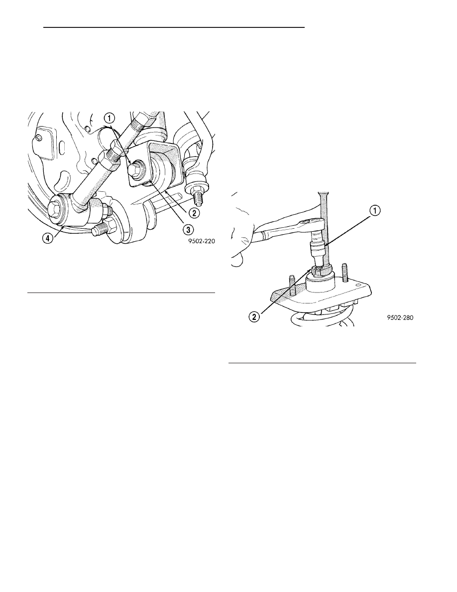
(7) Remove bolt attaching shock absorber to rear

knuckle (Fig. 15).

(8) Remove the shock absorber from the rear

knuckle first when removing the shock absorber from
vehicle by pushing down on the rear suspension.

(9) Move shock assembly downward and tilt top of

shock outward, then remove shock assembly from
vehicle through top of wheel opening.

DISASSEMBLY - SHOCK ASSEMBLY

The shock assembly must be removed from the

vehicle for it to be disassembled and assembled.
(Refer

to

2

-

SUSPENSION/REAR/SHOCK

-

REMOVAL)

For the disassembly and assembly of the shock

assembly, use strut spring compressor Pentastar Ser-
vice Equipment (PSE) tool W-7200, or the equivalent,
to compress the coil spring. Follow the manufactur-
er’s instructions closely.

WARNING: DO NOT REMOVE THE SHOCK ROD
NUT BEFORE THE COIL SPRING IS COMPRESSED.
THE COIL SPRING IS HELD UNDER PRESSURE
AND MUST BE COMPRESSED, REMOVING SPRING
TENSION FROM THE UPPER MOUNTING BRACKET
BEFORE THE ROD NUT IS REMOVED.

(1) If both shocks are being serviced at the same

time, mark the coil spring and shock assembly

according to which side of the vehicle the shock was
removed from, and which shock the coil spring was
removed from.

(2) Position the shock assembly in the strut coil

spring

compressor

following

the

manufacturer’s

instructions. Set the lower hooks and install the
clamp on the lower end of the coil spring, so the
shock is held in place once the shock shaft nut is
removed. Lower the upper hooks and position them
on the coil spring near the top.

(3) Compress the coil spring until all coil spring

tension is removed from the upper mounting bracket.

(4) Hold the shock rod from rotating using special

socket Snap-On

t A136, or equivalent, and remove the

retainer nut.

(5) Remove the upper shock rod bushing retainer

washer from the shock rod.

(6) Remove the upper shock mount and the rod

isolator bushings as an assembly from the rod of the
shock absorber.

(7) Remove the upper coil spring isolator from the

top of the coil spring.

(8) Remove the lower shock rod bushing washer

from the top of the dust boot and shock absorber rod.

(9) Remove the dust shield and cup as an assem-

bly from the shock absorber rod by pulling both
straight up and off the shock rod.

(10) Remove the clamp from the bottom of the coil

spring and remove the shock absorber, lower spring
isolator, jounce bumper, and collar out through the
bottom of the coil spring.

Fig. 15 Shock Absorber Attachment To Knuckle

1 - ATTACHING BOLT
2 - REAR KNUCKLE
3 - SHOCK ABSORBER CLEVIS BRACKET
4 - LATERAL LINK

Fig. 16 Retainer Nut Removal/Installation (Typical)

1 - SHOCK ABSORBER SOCKET
2 - CROW FOOT

JR

REAR SUSPENSION

2 - 41

SHOCK ASSEMBLY (Continued)

(11) Remove the jounce bumper and the collar

(Fig. 17) from the rod of the shock absorber.

(12) Remove the lower coil spring isolator (Fig. 18)

from the lower spring seat on the shock absorber.

(13) Remove the upper shock rod isolator bushing

and sleeve from the upper shock mount.

(14) Remove the lower shock rod isolator bushing

from the upper shock mount.

(15) Inspect the shock assembly components for

the following and replace as necessary:

• Inspect the shock for any condition of rod bind-

ing over the full stroke of the shaft.

• Check the upper shock mount for cracks and dis-

tortion, and locating studs for any sign of damage.

• Check the upper and lower shock rod isolator

bushings for severe deterioration of the rubber.

• Check the upper and lower coil spring isolators

for severe deterioration.

• Inspect the dust shield for rips and deteriora-

tion.

• Inspect the jounce bumper for cracks and signs

of deterioration.

• Inspect the coil spring for any sign of damage to

the coating.

(16) If the coil spring needs to be serviced, release

the tension from the coil spring by backing off the
compressor drive fully. Push back the compressor
upper hooks and remove the coil spring from the
compressor.

ASSEMBLY - SHOCK ASSEMBLY

(1) If the coil spring has been removed from the

compressor, place the lower end (smaller diameter) of
the coil spring in the spring compressor supported by
the lower hooks at the same position as in disassem-
bly, following the manufacturer’s instructions.

(2) Position the upper hooks of the spring compres-

sor on the coil spring near the top as in disassembly.

(3) Compress the coil spring enough to reinstall

the shock absorber and upper mount.

(4) Install the lower shock rod isolator bushing in

the bottom of the upper shock mount. The smaller
end is to be pointed away from the mount when
installed.

(5) Install the upper shock rod isolator bushing

and sleeve in the upper shock mount until seated
into lower bushing. The smaller end of the bushing is
to be pointed away from the mount when installed.

(6) Install the lower coil spring isolator on the

lower spring seat of the shock absorber (Fig. 18).

(7) Install the jounce bumper as shown on the rod

of the shock absorber (Fig. 19).

Fig. 17 Shock Absorber Jounce Bumper And Collar

1 - COLLAR
2 - SHOCK ABSORBER ROD
3 - SHOCK ABSORBER
4 - JOUNCE BUMPER

Fig. 18 Lower Coil Spring Isolator

1 - SHOCK ABSORBER
2 - COIL SPRING ISOLATOR

Fig. 19 Jounce Bumper Installed

1 - SHOCK ABSORBER ROD
2 - SHOCK ABSORBER JOUNCE BUMPER
3 - SHOCK ABSORBER

2 - 42

REAR SUSPENSION

JR

SHOCK ASSEMBLY (Continued)

(8) Install the collar on the rod of the shock

absorber assembly with the undercut side of sleeve
facing down (Fig. 20). Push the collar down until
seated on the step of the shock absorber rod.

(9) Install the shock through the bottom of the coil

spring until the lower spring seat contacts the lower
end of the coil spring. Install the clamp temporarily
securing the shock absorber to the coil spring.

(10) Install dust shield and cup over the jounce

bumper and onto the rod of the shock absorber.

(11) Install the lower shock rod bushing retainer

washer on the shock absorber rod.

(12) Install the upper spring isolator on the top of

the coil spring. The bottom of the isolator is con-
toured to fit around the inside diameter of the coil
spring and has a step built into it that the end of the
coil spring must fit into upon installation.

(13) Install the upper shock mount bracket and

rod isolator bushings as an assembly on the top of
the rod of the shock absorber.

(14) Install the upper shock rod bushing retainer

washer. Make sure the concave side is facing up.

(15) Install the shock assembly retainer nut. Hold

the shock rod from rotating using special socket
Snap-On

t A136, or equivalent, and tighten the

retainer nut using a crow foot wrench (on the end of
a torque wrench and extension) to a torque of 55 N·m
(40 ft. lbs.) (Fig. 16).

(16) Position the upper shock mount so it’s studs

are in line with the bolt hole in the shock absorber
lower bracket.

(17) Slowly release the tension from the coil spring

by backing off the compressor drive fully. As the ten-
sion is relieved, make sure the upper mount, isolator,
and coil spring align properly. Remove the clamp
from the lower end of the coil spring and shock. Push

back the spring compressor upper and lower hooks,
then remove the shock assembly from the spring
compressor.

(18) Install shock assembly on the vehicle. (Refer

to 2 - SUSPENSION/REAR/SHOCK - INSTALLA-
TION)

INSTALLATION - SHOCK ASSEMBLY

(1) Install shock assembly back in vehicle using

the reverse sequence of removal.

(2) Install upper shock mount into the mounting

holes in rear shock tower.

(3) Push down on rear knuckle to obtain clearance

and then install shock absorber clevis bracket on
rear knuckle.

(4) Align clevis bracket on shock absorber with

bushing in knuckle. Install and tighten bolt to a
torque of 95 N·m (70 ft. lbs.).

(5) Lower vehicle far enough to gain access to the

trunk.

(6) Install and tighten the 2 shock assembly upper

mounting nuts to a torque of 54 N·m (40 ft. lbs.).

(7) Install plastic cover on shock assembly.
(8) Install carpeting back on shock tower.
(9) Install fasteners securing splash shield to

shock mount.

(10) Install wheel and tire assembly on vehicle.

Install all wheel mounting nuts in proper sequence
until all nuts are torqued to half specification.
Repeat tightening sequence to full specified torque of
135 N·m (100 ft. lbs.).

(11) Lower vehicle to the ground.

STABILIZER BAR

DESCRIPTION

Some vehicles are equipped with a rear stabilizer

bar. The stabilizer bar interconnects the forward lat-
eral links of the vehicle’s rear suspension and is
attached to the rear suspension crossmember of the
vehicle.

Attachment of the stabilizer bar to the rear cross-

member of the vehicle is through 2 rubber-isolator
bushings and bushing retainers. The stabilizer bar to
lateral link attachment is done utilizing a rubber iso-
lated stabilizer bar attaching link. All parts of the
stabilizer bar are serviceable, and the stabilizer bar
to rear suspension isolator bushings are split for easy
removal and installation. The split in the stabilizer
bar to crossmember bushing must be positioned
toward the front of the vehicle, when the stabilizer
bar is installed on the vehicle.

Fig. 20 Installing Collar On Shock

1 - COLLAR
2 - UNDERCUT
3 - SHOCK ABSORBER ROD STEP

JR

REAR SUSPENSION

2 - 43

SHOCK ASSEMBLY (Continued)

OPERATION

Jounce and rebound movements affecting one rear

wheel of the vehicle are partially transmitted to the
opposite wheel of the vehicle through the stabilizer
bar to stabilize body roll.

DIAGNOSIS AND TESTING - STABILIZER BAR

Inspect the stabilizer bar for damage or bending.
Inspect for broken or distorted stabilizer bar bush-

ings, and bushing retainers. When inspecting the sta-
bilizer bar bushings, be sure that the slit in the
bushings are positioned so that it is facing toward
the front of the vehicle.

Inspect the bushings and sleeves in the stabilizer

bar attaching links for damage or deterioration.
Inspect the stabilizer bar attaching link to ensure it
is not bent or broken. If any of these conditions are
present when inspecting the attaching links, replace-
ment of the attaching link is required.

REMOVAL

(1) Raise vehicle on jackstands or centered on a

frame contact type hoist. (Refer to LUBRICATION &
MAINTENANCE/HOISTING - STANDARD PROCE-
DURE).

(2) Remove both rear wheel and tire assemblies

from the vehicle.

(3) From each side of the vehicle, remove the nut

(Fig. 21) attaching the stabilizer bar attaching link/
isolator bushings to the stabilizer bar.

(4) Remove the 4 bolts attaching the stabilizer bar

bushing clamps to the rear suspension crossmember
(Fig. 22).

(5) Remove the rear stabilizer bar to crossmember

bushing clamps and bushings from the stabilizer bar.

(6) Remove stabilizer bar from vehicle. Stabilizer

bar will come out of vehicle between the exhaust pipe
and the rear suspension crossmember.

STABILIZER BAR BUSHING INSPECTION

Inspect for broken or distorted retainers and bush-

ings. If bushing replacement is required, bushings
can be removed by opening slit in bushing and
removing bushing from around stabilizer bar.

INSTALLATION

(1) Install stabilizer bar back in vehicle with the

bushings removed using the reverse sequence of
removal.

(2) When stabilizer bar is installed in vehicle, it

must be installed with the bend in the end of the sta-
bilizer bar positioned up in vehicle when viewed from
the side (Fig. 23).

Fig. 21 Stabilizer Bar Attaching Link

1 - PARK BRAKE CABLE
2 - STABILIZER BAR ATTACHING LINK
3 - NUT
4 - STABILIZER BAR
5 - REAR LATERAL LINK
6 - FORWARD LATERAL LINK

Fig. 22 Stabilizer Bar Attachment To Rear Suspension

1 - ATTACHING BOLT
2 - REAR SUSPENSION CROSSMEMBER
3 - ATTACHING BOLT
4 - ATTACHING BOLT
5 - REAR STABILIZER BAR
6 - STABILIZER BAR ATTACHING BRACKETS
7 - ATTACHING BOLT

Fig. 23 Installed Positioning

1 - INCORRECTLY INSTALLED POSITION OF STABILIZER BAR
2 - CORRECTLY INSTALLED POSITION OF STABILIZER BAR

2 - 44

REAR SUSPENSION

JR

STABILIZER BAR (Continued)


Content   ..  270  271  272  273   ..