Chrysler Sebring, Stratus sedan, Sebring Convertible. Manual - part 270
CAUTION: Only frame contact or wheel lift hoisting
equipment can be used on vehicles having a fully
independent rear suspension. Vehicles with inde-
pendent rear suspension can not be hoisted using
equipment designed to lift a vehicle by the rear
axle. If this type of hoisting equipment is used dam-
age to rear suspension components will occur.
NOTE: If a rear suspension component becomes
bent, damaged or fails, no attempt should be made
to straighten or repair it. Always replace it with a
new component.
SPECIFICATIONS
REAR SUSPENSION FASTENER TORQUE
DESCRIPTION
TORQUE
Shock Assembly:
Body Mounting Nuts
54 N·m (40 ft. lbs.)
Knuckle Bolt/Nut
95 N·m (70 ft. lbs.)
Rod To Upper Mount Nut
55 N·m (40 ft. lbs.)
Knuckle:
Brake Adapter Mounting
Bolts
61 N·m (45 ft. lbs.)
Hub And Bearing:
Knuckle Retaining Nut
250 N·m (185 ft. lbs.)
Wheel Mounting Nuts
135 N·m (100 ft. lbs.)
Upper Control Arm:
Pivot Bar To
Crossmember
95 N·m (70 ft. lbs.)
Lateral Links:
To Knuckle Nuts
122 N·m (90 ft. lbs.)
Jam Nuts
95 N·m (70 ft. lbs.)
To Suspension
Crossmember Nuts
88 N·m (65 ft. lbs.)
Trailing Link:
Shaft Nuts (Front And
Rear)
115 N·m (85 ft. lbs.)
Bracket To Body
Mounting Bolts
29 N·m (21 ft. lbs.)
Ball Joint:
DESCRIPTION
TORQUE
Stud Nut
27 N·m (20 ft. lbs.)
Rear Suspension Crossmember:
Body Attaching Bolts
108 N·m (80 ft. lbs.)
Stabilizer Bar:
Isolator Bushing Retainer
Bolt
32 N·m (24 ft. lbs.)
Lateral Link Stabilizer
Link Nut
31 N·m (23 ft. lbs.)
Bracket To Crossmember
Bolts
32 N·m (24 ft. lbs.)
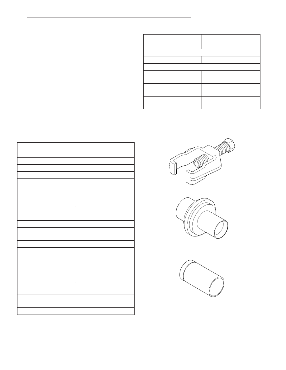
SPECIAL TOOLS
REAR SUSPENSION
Puller, Pitman Arm CT-1106
Remover, Suspension Arm Bushing And Ball Joint
6804
Installer, Ball Joint
JR
REAR SUSPENSION
2 - 33
REAR SUSPENSION (Continued)