Chrysler Sebring, Stratus sedan, Sebring Convertible. Manual - part 269


  Index      Chrysler     Chrysler Sebring, Stratus sedan, Sebring Convertible - service repair manual 2001-2007 year


Search            


Content   ..  267  268  269  270   ..


Chrysler Sebring, Stratus sedan, Sebring Convertible. Manual - part 269


(11) Lower the vehicle.

STABILIZER BAR

DESCRIPTION

The stabilizer bar interconnects both front lower

control arms of the vehicle and is attached to the
front suspension cradle and the underbody of the
vehicle.

Attachment of the stabilizer bar to the front sus-

pension cradle is through 2 rubber-isolator bushings
and bushing retainers. The stabilizer bar to lower
control arm attachment is done utilizing a ball joint
type, stabilizer bar attaching link. All parts of the
stabilizer bar are replaceable as individual compo-
nents, and the bushings attaching the stabilizer bar
to crossmember are split for easy removal and instal-
lation.

OPERATION

Jounce and rebound movements affecting one

wheel are partially transmitted to the opposite wheel
of the vehicle to stabilize body roll through the stabi-
lizer bar.

DIAGNOSIS AND TESTING - STABILIZER BAR

Inspect for broken or distorted stabilizer bar bush-

ings, bushing retainers, and worn or damaged stabi-
lizer bar to control arm attaching links.

REMOVAL

REMOVAL - STABILIZER BAR

(1) Raise vehicle on jack stands or centered on a

frame contact type hoist. (Refer to LUBRICATION &
MAINTENANCE/HOISTING - SERVICE PROCE-
DURE).

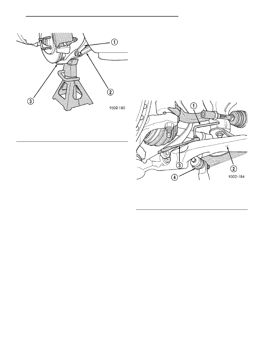
(2) Remove nuts and stabilizer bar attaching link

assemblies from the front lower control arms (Fig.
56). When removing attaching link nut, keep stud
from turning by installing an allen wrench in the end
of the stud (Fig. 56).

(3) Remove the 4 bolts attaching the stabilizer bar

bushing retainers to the front suspension crossmem-
ber and body (Fig. 57). Then remove the stabilizer
bar assembly from the vehicle.

STABILIZER BAR INSPECTION

Inspect for broken or distorted stabilizer bar bush-

ings, clamps and attaching links. If stabilizer bar to
front crossmember bushing replacement is required,
bushing can be removed using the stabilizer bar
bushing removal procedure in the Disassembly And
Assembly section in this group of the service manual.

If inspection determines that replacement of a sta-

bilizer bar to lower control arm attachment link is
required, replace the link before installing stabilizer
bar.

REMOVAL - STABILIZER BAR BUSHING
(FRONT)

(1) Bend back the 4 crimp locations on the stabi-

lizer bar bushing retainer (Fig. 58).

(2) Separate the stabilizer bar bushing retainer.

Fig. 55 Lower Control Arm Correctly Supported By

Jack Stand

1 - SHOCK ABSORBER CLEVIS
2 - LOWER CONTROL ARM
3 - BALL JOINT CAP

Fig. 56 Stabilizer Bar Attaching Link Nut Removal

1 - ALLEN WRENCH
2 - LOWER CONTROL ARM
3 - WRENCH
4 - STABILIZER BAR LINK ASSEMBLY

JR

FRONT SUSPENSION

2 - 29

SHOCK ASSEMBLY (Continued)

(3) Stabilizer bar bushings are removed by opening

slit and peeling bushing off stabilizer bar.

INSTALLATION

INSTALLATION - STABILIZER BAR

(1) Position stabilizer bar and bushings as an

assembly into front crossmember. Install the stabi-
lizer bar bushing retainer to crossmember and body
attaching bolts (Fig. 57).

(2) Tighten the bushing retainer attaching bolts to

a torque of 61 N·m (45 ft. lbs.).

(3) Align stabilizer bar attaching link assemblies

with attaching link mounting holes in the lower con-
trol arms. Install stabilizer bar attaching links into
both lower control arms. Install the attaching link to
lower control arm retaining nuts. Torque the stabi-
lizer bar attaching link nuts to 105 N·m (77 ft. lbs.).

INSTALLATION - STABILIZER BAR BUSHING

(1) Install new stabilizer bar bushings on the sta-

bilizer bar. Bushings must be installed on sway
bar with slit in bushing facing front of vehicle
when sway bar is installed.

(2) Install bushing retainers back on stabilizer bar

bushings.

UPPER BALL JOINT

DESCRIPTION

The ball joint is pressed into the upper control arm

and has a tapered stud for attachment to the steer-
ing knuckle. The ball joint stud is attached and
locked into the steering knuckle using a special nut.
The ball joint is a sealed-for-life type and requires no
maintenance. If the ball joint is defective it will
require replacement of the entire upper control arm.

DIAGNOSIS AND TESTING - UPPER BALL
JOINT

(1) Raise and support vehicle so that tires clear

floor. (Refer to LUBRICATION & MAINTENANCE/
HOISTING - STANDARD PROCEDURE)

(2) Push inward and pull outward at top of tire

noting if any movement of ball joint occurs.

(3) If movement is noted, replace upper control

arm.

ALTERNATE METHOD

(1) Raise and support vehicle. (Refer to LUBRICA-

TION & MAINTENANCE/HOISTING - STANDARD
PROCEDURE)

(2) Remove tire and wheel assembly. (Refer to 22 -

TIRES/WHEELS - REMOVAL)

(3) Push inward and pull outward on neck of

knuckle near ball joint while observing ball joint for
movement. Holding a finger against knuckle and
upper control arm while performing this helps to
sense movement.

(4) If movement is noted, replace upper control

arm.

Fig. 57 Stabilizer Bar Bushing Retainer Attaching

Bolts

1 - STABILIZER BAR BUSHING CLAMP
2 - FRONT SUSPENSION CROSSMEMBER
3 - ATTACHING BOLTS
4 - STABILIZER BAR
5 - VEHICLE BODY

Fig. 58 Stabilizer Bar Bushing Retainer

1 - STABILIZER BAR BUSHING RETAINER
2 - CRIMPS
3 - STABILIZER BAR
4 - CRIMPS
5 - STABILIZER BAR BUSHING

2 - 30

FRONT SUSPENSION

JR

STABILIZER BAR (Continued)

UPPER CONTROL ARM

DESCRIPTION

The upper control arm is a high strength steel

stamping. The upper control arm uses the 2 rubber
bushings of the upper control arm/shock absorber
mounting bracket to isolate it from the mounting
bracket and the body of the vehicle. The upper con-
trol arm is bolted to the top of the steering knuckle
through the upper ball joint.

If damaged, the upper control arm is serviced only

as a complete component. Inspect the upper control
arm for any signs of damage. If control arm shows
any sign of damage the upper control arm must be
replaced. Do not attempt to repair or straighten a
broken or bent upper control arm.

OPERATION

The upper control arm supports the upper end of

the steering knuckle and allows for the up and down
movement of the suspension during the jounce and
rebound travel.

REMOVAL - UPPER CONTROL ARM

(1) Remove the front shock assembly from the

vehicle. (Refer to 2 - SUSPENSION/FRONT/SHOCK
- REMOVAL)

(2) Disassemble the shock assembly until the

upper (shock absorber/upper control arm) mounting
bracket is removed from the coil spring. (Refer to 2 -
SUSPENSION/FRONT/SHOCK - DISASSEMBLY)

(3) Remove the 2 bolts attaching the upper control

arm to the bushings in the upper mounting bracket
(Fig. 59).

(4) Remove the upper control arm from the mount-

ing bracket.

INSPECTION - UPPER CONTROL ARM

If damaged, the upper control arm is serviced only

as a complete component. Inspect the upper control
arm for any signs of damage. If control arm shows
any sign of damage the upper control arm must be
replaced. Do not attempt to repair or straighten a
broken or bent upper control arm.

INSTALLATION - UPPER CONTROL ARM

(1) Install the upper control arm on the upper

(shock

absorber/upper

control

arm)

mounting

bracket.

(2) Install the 2 bolts attaching the upper control

arm to the bushings in the mounting bracket (Fig.
59). The bolts must be installed from center, so the
heads are toward the coil spring when it is installed.
The bolts MUST be installed so the head of the
bolt will be toward the coil spring when the
mounting

bracket

is

installed

on

shock

absorber (Fig. 59).

CAUTION: For clearance reasons the control arm
mounting bolts must be installed from center, so
the heads are toward the coil spring when it is
installed. Otherwise the bolts may rub the coil
spring, damaging it.

(3) Install the control arm mounting bolt nuts.

Position the control arm at a 90 degree angle to the
mounting bracket and tighten the bolts to a torque of
90 N·m (66 ft. lbs.).

(4) Reinstall the upper mounting bracket and con-

trol arm on the coil spring. Reassemble the front
shock assembly. (Refer to 2 - SUSPENSION/FRONT/
SHOCK - ASSEMBLY)

(5) Reinstall the front shock assembly on the vehi-

cle. (Refer to 2 - SUSPENSION/FRONT/SHOCK -
INSTALLATION)

Fig. 59 Upper Control Arm To Mounting Bracket

Attachment

1 - CONTROL ARM MOUNTING BOLTS
2 - UPPER CONTROL ARM MOUNTING BRACKET
3 - UPPER CONTROL ARM

JR

FRONT SUSPENSION

2 - 31

REAR SUSPENSION

TABLE OF CONTENTS

page

page

REAR SUSPENSION

DESCRIPTION - REAR SUSPENSION

. . . . . . . 32

OPERATION - REAR SUSPENSION

. . . . . . . . . 32

WARNINGS AND CAUTIONS

. . . . . . . . . . . . . . 32

SPECIFICATIONS

REAR SUSPENSION FASTENER TORQUE

. . 33

SPECIAL TOOLS

REAR SUSPENSION

. . . . . . . . . . . . . . . . . . . 33

HUB / BEARING

DESCRIPTION

. . . . . . . . . . . . . . . . . . . . . . . . . 34

OPERATION

. . . . . . . . . . . . . . . . . . . . . . . . . . . 34

DIAGNOSIS AND TESTING - HUB AND

BEARING

. . . . . . . . . . . . . . . . . . . . . . . . . . . . 34

REMOVAL

. . . . . . . . . . . . . . . . . . . . . . . . . . . . . 34

INSTALLATION

. . . . . . . . . . . . . . . . . . . . . . . . . 34

KNUCKLE

DESCRIPTION

. . . . . . . . . . . . . . . . . . . . . . . . . 34

OPERATION

. . . . . . . . . . . . . . . . . . . . . . . . . . . 34

DIAGNOSIS AND TESTING - KNUCKLE

. . . . . . 34

REMOVAL

. . . . . . . . . . . . . . . . . . . . . . . . . . . . . 34

INSTALLATION

. . . . . . . . . . . . . . . . . . . . . . . . . 37

LATERAL LINK

DESCRIPTION

. . . . . . . . . . . . . . . . . . . . . . . . . 38

OPERATION

. . . . . . . . . . . . . . . . . . . . . . . . . . . 38

DIAGNOSIS AND TESTING - LATERAL LINKS

. 38

REMOVAL

. . . . . . . . . . . . . . . . . . . . . . . . . . . . . 38

INSTALLATION

. . . . . . . . . . . . . . . . . . . . . . . . . 39

SHOCK ASSEMBLY

DESCRIPTION - SHOCK ASSEMBLY

. . . . . . . . 40

OPERATION - SHOCK ASSEMBLY

. . . . . . . . . . 40

DIAGNOSIS AND TESTING - SHOCK

ASSEMBLY

. . . . . . . . . . . . . . . . . . . . . . . . . . 40

REMOVAL - SHOCK ASSEMBLY

. . . . . . . . . . . . 40

DISASSEMBLY - SHOCK ASSEMBLY

. . . . . . . . 41

ASSEMBLY - SHOCK ASSEMBLY

. . . . . . . . . . . 42

INSTALLATION - SHOCK ASSEMBLY

. . . . . . . . 43

STABILIZER BAR

DESCRIPTION

. . . . . . . . . . . . . . . . . . . . . . . . . 43

OPERATION

. . . . . . . . . . . . . . . . . . . . . . . . . . . 44

DIAGNOSIS AND TESTING - STABILIZER BAR

. 44

REMOVAL

. . . . . . . . . . . . . . . . . . . . . . . . . . . . . 44

INSTALLATION

. . . . . . . . . . . . . . . . . . . . . . . . . 44

TRAILING LINK

DESCRIPTION

. . . . . . . . . . . . . . . . . . . . . . . . . 45

OPERATION

. . . . . . . . . . . . . . . . . . . . . . . . . . . 45

DIAGNOSIS AND TESTING - TRAILING LINK

. . 45

REMOVAL

. . . . . . . . . . . . . . . . . . . . . . . . . . . . . 45

INSTALLATION

. . . . . . . . . . . . . . . . . . . . . . . . . 46

UPPER BALL JOINT

DESCRIPTION

. . . . . . . . . . . . . . . . . . . . . . . . . 47

DIAGNOSIS AND TESTING - UPPER BALL

JOINT

. . . . . . . . . . . . . . . . . . . . . . . . . . . . . . 47

UPPER CONTROL ARM

DESCRIPTION

. . . . . . . . . . . . . . . . . . . . . . . . . 47

OPERATION

. . . . . . . . . . . . . . . . . . . . . . . . . . . 47

REMOVAL

. . . . . . . . . . . . . . . . . . . . . . . . . . . . . 47

DISASSEMBLY - UPPER BALL JOINT

. . . . . . . . 50

INSPECTION

. . . . . . . . . . . . . . . . . . . . . . . . . . 50

ASSEMBLY - UPPER BALL JOINT

. . . . . . . . . . 50

INSTALLATION

. . . . . . . . . . . . . . . . . . . . . . . . . 51

REAR SUSPENSION

DESCRIPTION - REAR SUSPENSION

The rear suspension used on this vehicle is a fully

independent short and long arm style suspension.
Each side of the rear suspension consists of these
major components:

• a shock assembly

• a knuckle

• an upper control arm

• two lateral links

• a trailing link

• a stabilizer bar (one per vehicle shared by each

side)

OPERATION - REAR SUSPENSION

The rear suspension allows each rear wheel on

vehicle to adapt to different road surfaces and condi-
tions without affecting the control of the vehicle.
Each side of the suspension is allowed to move inde-
pendently from the other.

WARNINGS AND CAUTIONS

WARNING: DO NOT REMOVE A SHOCK ROD NUT
WHILE THE SHOCK ASSEMBLY IS INSTALLED IN
VEHICLE, OR BEFORE THE SHOCK ASSEMBLY
SPRING IS COMPRESSED.

2 - 32

REAR SUSPENSION

JR


Content   ..  267  268  269  270   ..