Chrysler Pacifica. Manual - part 684
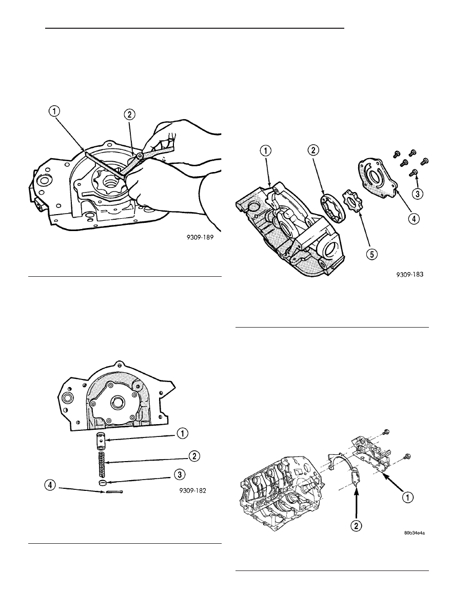
(8) Place a straightedge across the face of the body,
between bolt holes. If a feeler gauge of 0.077 mm
(0.003 in.) or more can be inserted between rotors
and the straightedge, replace pump assembly (Fig.
150) ONLY if rotors are in specs.
(9) Inspect oil pressure relief valve plunger for
scoring and free operation in its bore. Small marks
may be removed with 400-grit wet or dry sandpaper.
(10) The relief valve spring (Fig. 151) has a free
length of approximately 49.5 mm (1.95 in.) it should
test between 101–110 N (23–25 lbs.) when com-
pressed to 34 mm (1–11/32 in.). Replace spring that
fails to meet specifications.
(11) Assemble oil pump. (Refer to 9 - ENGINE/LU-
BRICATION/OIL PUMP - ASSEMBLY)
ASSEMBLY
(1) Assemble oil pump using new parts as required.
(2) Tighten cover screws to 12 N·m (105 in. lbs.)
(Fig. 152).
(3) Prime oil pump before installation by filling
rotor cavity with engine oil.
(4) If oil pressure is low and pump is within spec-
ifications, inspect for worn engine bearings or other
reasons for oil pressure loss.
INSTALLATION
NOTE:
Thoroughly
clean
all
bolt
threads
and
threaded area in the engine, removing all oil resi-
due, before assembly.
(1) Prime oil pump before installation by filling
rotor cavity with clean engine oil.
(2) Install oil pump and gasket carefully over the
crankshaft and position pump onto block (Fig. 153).
Fig. 150 Measuring Clearance Over Rotors
1 - STRAIGHT EDGE
2 - FEELER GAUGES
Fig. 151 Oil Pressure Relief Valve
1 - RELIEF VALVE
2 - SPRING
3 - RETAINER CAP
4 - COTTER PIN
Fig. 152 Oil Pump
1 - OIL PUMP BODY
2 - OIL PUMP OUTER ROTOR
3 - SCREWS
4 - OIL PUMP COVER
5 - OIL PUMP INNER ROTOR
Fig. 153 OIL PUMP
1 - OIL PUMP
2 - GASKET
CS
ENGINE 3.5L
9 - 91
OIL PUMP (Continued)