Chrysler Pacifica. Manual - part 685


  Index      Chrysler     Chrysler Pacifica - service repair manual 2005 year


Search            


Content   ..  683  684  685  686   ..


Chrysler Pacifica. Manual - part 685


(8) Install the EGR tube (Refer to 25 - EMIS-

SIONS CONTROL/EXHAUST GAS RECIRCULA-
TION/VALVE - INSTALLATION).

(9) Connect vacuum lines to the following (Fig.

156):

• Positive Crankcase Ventilation (PCV) Valve

• EVAP Purge Solenoid

• Power Brake Booster
(10) Install alternator support bracket (Fig. 156).
(11) Connect electrical connectors to the following

(Fig. 157):

• Manifold Tuning Valve (MTV)

• Exhaust Gas Recirculation (EGR)

• Throttle Position Sensor (TPS)

• Idle Air Control (IAC)

• Manifold Absolute Pressure (MAP)
(12) Install the throttle and speed control cable

bracket and retaining bolts.

(13) Install throttle and speed control cables to

bracket and throttle arm. (Refer to 14 - FUEL SYS-
TEM/FUEL

INJECTION/THROTTLE

CONTROL

CABLE - INSTALLATION)

(14) Install air cleaner housing and inlet hose.
(15) Install the engine cover.
(16) Connect negative battery cable.

EXHAUST MANIFOLD - LEFT

REMOVAL - LEFT EXHAUST MANIFOLD

(1) Disconnect and isolate the negative battery

cable.

(2) Remove the radiator close out panel.
(3) Remove the radiator core support (Refer to 23 -

BODY/EXTERIOR/GRILLE OPENING REINFORCE-
MENT - REMOVAL).

(4) Remove the radiator cooling fan assembly.
(5) Loosen the oil level indicator tube retaining

bolt and position the dipstick out of the way.

(6) Remove the exhaust manifold crossover pipe

retaining bolts (Refer to 9 - ENGINE/MANIFOLDS/
EXHAUST MANIFOLD - REMOVAL).

(7) Remove the exhaust manifold retaining bolts,

exhaust manifold, and discard gasket.

INSPECTION

(1) Inspect

exhaust

manifolds

for

damage

or

cracks.

(2) Check manifold flatness.
(3) Inspect the exhaust manifold gasket for obvi-

ous discoloration or distortion.

(4) Check distortion of the cylinder head mounting

surface with a straightedge and thickness gauge.

INSTALLATION - LEFT EXHAUST MANIFOLD

(1) Position the exhaust manifold and gasket.

Install the retaining bolts. Tighten bolts starting at
the center working outward to 23 N.m (200 in. lbs.)
(Fig. 161).

(2) Install the exhaust manifold crossover pipe

retaining bolts. Tighten bolts to 31 N.m (275 in. lbs.).

(3) Position the oil dipstick tube and install the

retaining bolt.

(4) Install the radiator cooling fan assembly.
(5) Install the radiator closure panel crossmember

(Refer to 23 - BODY/EXTERIOR/GRILLE OPENING
REINFORCEMENT - INSTALLATION).

(6) Install the radiator close out panel.
(7) Connect the negative battery cable.

EXHAUST MANIFOLD - RIGHT

REMOVAL - RIGHT EXHAUST MANIFOLD

(1) Disconnect the negative battery cable.
(2) Disconnect the upstream oxygen sensor electri-

cal connector.

(3) Remove the exhaust manifold crossover pipe

retaining bolts (Fig. 162).

(4) Raise and support the vehicle.
(5) Disconnect the downstream oxygen sensor elec-

trical connector.

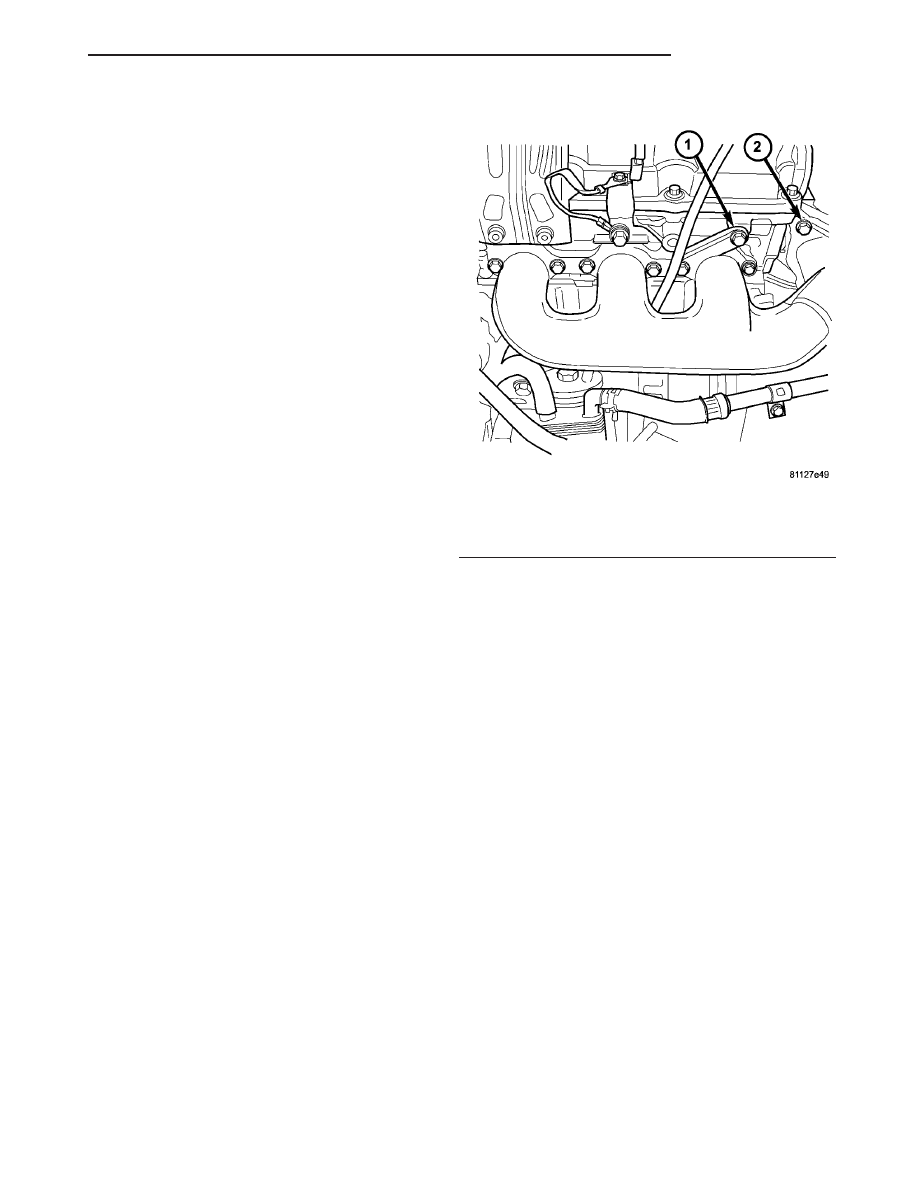
Fig. 161 LEFT EXHAUST MANIFOLD

1 - OIL LEVEL INDICATOR TUBE RETAINING BOLT
2 - EXHAUST CROSS OVER PIPE UNION

CS

ENGINE 3.5L

9 - 95

INTAKE MANIFOLD (Continued)

(6) Remove the exhaust manifold flange retaining

bolts and disconnect the exhaust system hangers
from the pipe assembly.

(7) Remove the exhaust system from the vehicle.
(8) Remove the EGR tube support bracket bolt

(Fig. 162).

(9) Remove the lower exhaust manifold retaining

bolts (Fig. 162).

(10) Remove the oxygen sensor from the exhaust

manifold.

INSTALLATION - RIGHT EXHAUST MANIFOLD

(1) Clean gasket surfaces.
(2) Position the exhaust manifold and gasket.

Install the retaining bolts. Tighten bolts starting at
the center working outward to 23 N.m (200 in. lbs.)
(Fig. 162).

(3) Install exhaust system. Connect the exhaust

system hangers from the pipe assembly and install
the three exhaust manifold flange retaining bolts.
Tighten the bolts to 30 N.m (22 ft. lbs.).

(4) Connect the downstream oxygen sensor electri-

cal connector.

(5) Install the EGR tube retaining bracket (Fig.

162).

(6) Lower vehicle.
(7) Install the exhaust manifold crossover pipe

retaining bolts. Tighten bolts to 31 N.m (275 in. lbs.)
(Fig. 162).

(8) Connect the upstream oxygen sensor electrical

connector.

(9) Connect the negative battery cable.

CROSSOVER PIPE - EXHAUST
MANIFOLD

REMOVAL

(1) Remove the bolts and nuts attaching the cross-

over pipe the manifolds (Fig. 163).

(2) Remove the crossover pipe and gaskets. Dis-

card the gaskets.

INSTALLATION

(1) Position new gasket on left exhaust manifold.
(2) Position cross-over pipe to the manifold connec-

tions.

(3) Position new gasket on right exhaust manifold

and install the bolts. Tighten bolts to 41 N.m (30 ft.
lbs.)

(4) Install and tighten nuts to 41 N·m (30 ft. lbs.).

(Fig. 163)

(5) Install coolant recovery container (Refer to 7 -

COOLING/ENGINE/COOLANT RECOVERY CON-
TAINER - INSTALLATION).

Fig. 162 EGR VALVE AND TUBE

1 - EGR TUBE
2 - IGNITION COIL
3 - CYLINDER HEAD COVER
4 - RIGHT EXHAUST MANIFOLD
5 - EGR VALVE

Fig. 163 EXHAUST CROSS OVER PIPE

1 - CROSS OVER PIPE

9 - 96

ENGINE 3.5L

CS

EXHAUST MANIFOLD - RIGHT (Continued)

VALVE TIMING

DESCRIPTION

The timing drive system has been designed to pro-

vide quiet performance and reliability to support a
NON free-wheeling engine.

The timing drive components include a crankshaft

sprocket,

camshaft

sprockets,

tensioner

pulley,

hydraulic tensioner and a timing belt. The water
pump is driven by the back side of the timing belt.
The right and left camshaft sprockets are keyed and
not interchangeable because of the cam sensor
pick-up wheel on the left sprocket (Fig. 164).

FRONT TIMING BELT COVER

REMOVAL

(1) Perform fuel pressure release procedure. (Refer

to 14 - FUEL SYSTEM/FUEL DELIVERY - STAN-
DARD PROCEDURE).

(2) Disconnect negative battery cable.
(3) Raise vehicle on hoist.
(4) Remove accessory drive belt (Refer to 7 -

COOLING/ACCESSORY

DRIVE/DRIVE

BELTS

-

REMOVAL).

(5) Remove accessory drive belt tensioner.
(6)

Remove bolts for power steering pump. Repo-

sition power steering pump aside.

(7) Remove crankshaft damper (Refer to 9 -

ENGINE/ENGINE BLOCK/VIBRATION DAMPER -
REMOVAL).

(8) Remove the lower front timing belt cover fas-

teners (Fig. 165).

(9) Lower the vehicle.
(10)

Support the engine with a floor jack.

(11) Remove the air cleaner housing (Refer to 9 -

ENGINE/AIR

INTAKE

SYSTEM/AIR

CLEANER

HOUSING - REMOVAL).

(12) Remove the front engine mount (Refer to 9 -

ENGINE/ENGINE MOUNTING/FRONT MOUNT -
REMOVAL).

(13) Disconnect the fuel supply line at the fuel rail

(Fig. 166).

(14) Remove the upper timing belt cover bolts and

remove front timing belt cover (Refer to 9 - ENGINE/
AIR INTAKE SYSTEM/AIR CLEANER HOUSING -
REMOVAL).

INSTALLATION

NOTE: The timing cover bolts and both holes to the
engine block must be thoroughly cleaned and free
of oil residue before assembly. IN ADDITION add
thread sealant to the timing cover bolts that mount
to the oil pump (Refer to 9 - ENGINE/LUBRICATION/
OIL PUMP - INSTALLATION).

(1) Install front timing belt cover (Fig. 164).

Fig. 164 TIMING DRIVE SYSTEM

1 - FRONT TIMING COVER
2 - WATER PUMP
3 - TIMING BELT
4 - CRANKSHAFT SPROCKET
5 - CRANKSHAFT DAMPER

Fig. 165 LOWER TIMING BELT FRONT COVER

1 - POWER STEERING HOSE
2 - TIMING BELT TENSIONER
3 - IDLER PULLEY

CS

ENGINE 3.5L

9 - 97

(2) Install the upper engine mount (Refer to 9 -

ENGINE/ENGINE MOUNTING/FRONT MOUNT -
INSTALLATION).

(3) Connect fuel supply line at fuel rail (Fig. 166).
(4) Install the air cleaner housing (Refer to 9 -

ENGINE/AIR

INTAKE

SYSTEM/AIR

CLEANER

HOUSING - INSTALLATION).

(5) Remove floor jack and raise vehicle.
(6) Install power steering pump fasteners. Tighten

bolts to 23 N·m (200 lbs. in..).

(7) Install

crankshaft

damper

(Refer

to

9

-

ENGINE/ENGINE BLOCK/VIBRATION DAMPER -
INSTALLATION).

(8) Install accessory drive belt tensioner. Torque

fastener to 28 N·m (250 in. lbs.).

(9) Install accessory drive belt (Refer to 7 - COOL-

ING/ACCESSORY DRIVE/DRIVE BELTS - INSTAL-
LATION).

(10) Lower vehicle.
(11) Connect negative battery cable.

REAR TIMING BELT COVER

REMOVAL

(1) Perform fuel pressure release procedure. (Refer

to 14 - FUEL SYSTEM/FUEL DELIVERY - STAN-
DARD PROCEDURE).

(2) Disconnect the negative battery cable.
(3) Remove timing belt (Refer to 9 - ENGINE/

VALVE

TIMING/TIMING

BELT/CHAIN

AND

SPROCKETS - REMOVAL).

(4) Remove camshaft sprockets (Refer to 9 -

ENGINE/VALVE

TIMING/TIMING

BELT/CHAIN

AND SPROCKETS - REMOVAL).

(5) Remove rear timing belt cover bolts (Fig. 167).
(6) Remove the rear cover.

NOTE: The rear timing belt cover has O-rings to
seal the water pump passages to cylinder block
(Fig. 167). Do not reuse the O-rings.

Fig. 166 UPPER TIMING BELT FRONT COVER

1 - FUEL RAIL
2 - GENERATOR
3 - IDLER PULLEY
4 - FUEL SUPPLY LINE

Fig. 167 Rear Timing Belt Cover Fasteners

1 - M8 FASTENERS (APPLY THREAD SEALANT)
2 - M10 FASTENERS
3 - M6 FASTENERS
4 - REAR TIMING BELT COVER
5 - M10 FASTENERS (STUD/NUT)

9 - 98

ENGINE 3.5L

CS

FRONT TIMING BELT COVER (Continued)


Content   ..  683  684  685  686   ..