Chrysler Pacifica. Manual - part 682


  Index      Chrysler     Chrysler Pacifica - service repair manual 2005 year


Search            


Content   ..  680  681  682  683   ..


Chrysler Pacifica. Manual - part 682


ENGINE OIL COOLER

DESCRIPTION

The engine oil cooler is a coolant-to-oil type and is

mounted between the oil filter and the oil filter
adapter (Fig. 128).

OPERATION

Engine oil travels from the oil cooler and into the

oil filter. Engine oil then exits the filter into the main
gallery. Engine coolant flows into the cooler from the
heater return tube and exits into the water inlet
tube.

REMOVAL

(1) Drain cooling system (Refer to 7 - COOLING/

ENGINE/COOLANT - STANDARD PROCEDURE).

(2) Raise vehicle on hoist.
(3) Disconnect coolant hoses from oil cooler.
(4) Remove oil filter.
(5) Remove oil cooler attaching fastener from cen-

ter of oil cooler.

(6) Remove oil cooler (Fig. 129).

INSTALLATION

(1) Lubricate seal and position oil cooler to fitting

on oil filter adapter (Fig. 130).

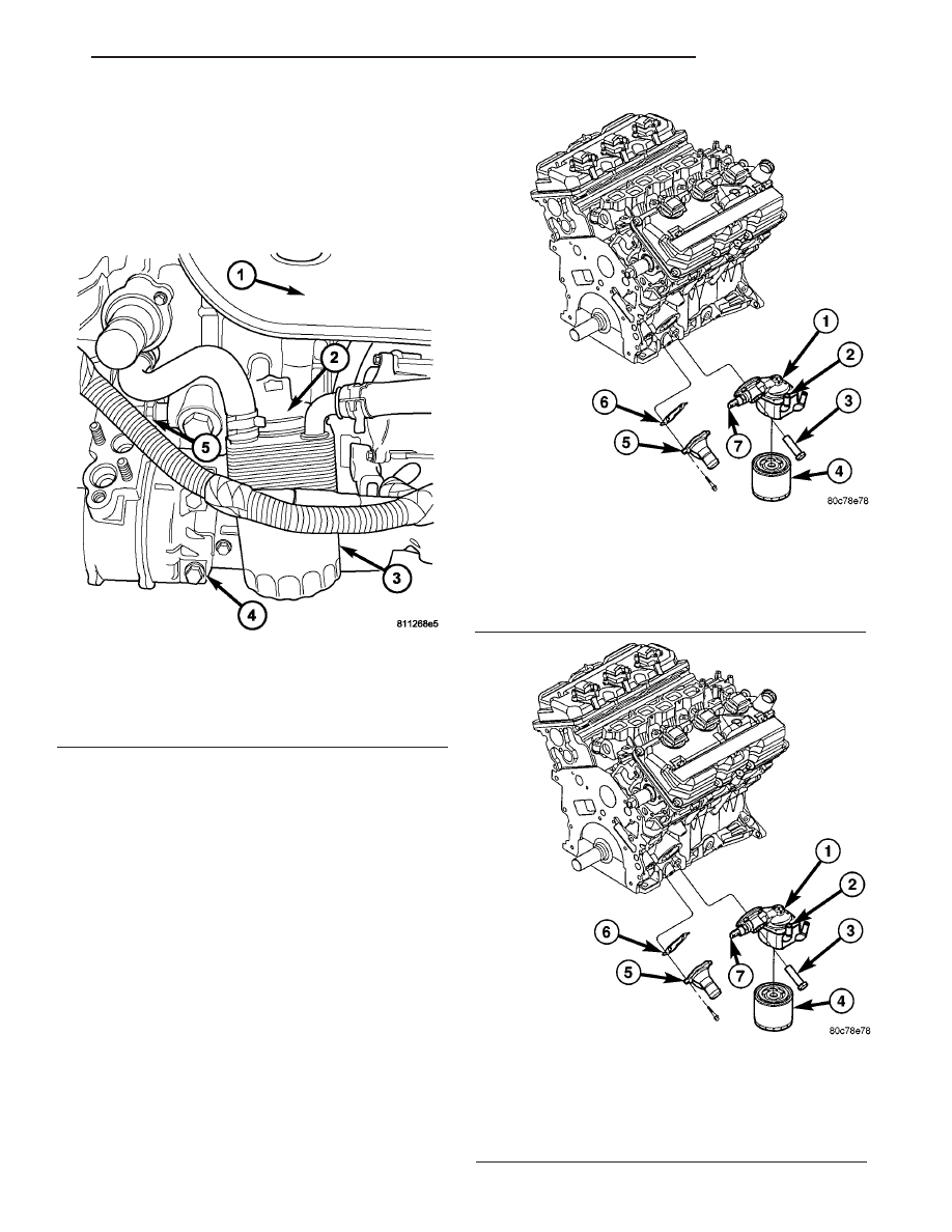
Fig. 129 Engine Oil Cooler and Filter Ad

1 - OIL FILTER ADAPTER
2 - OIL COOLER
3 - FASTENER - OIL FILTER ADAPTER
4 - OIL FILTER
5 - WATER INLET TUBE
6 - GASKET
7 - OIL PRESSURE SENSOR

Fig. 130 Engine Oil Cooler and Filter Adapter

1 - OIL FILTER ADAPTER
2 - OIL COOLER
3 - FASTENER - OIL FILTER ADAPTER
4 - OIL FILTER
5 - WATER INLET TUBE
6 - GASKET
7 - OIL PRESSURE SENSOR

Fig. 128 ENGINE OIL FILTER AND COOLER

1 - EXHAUST MANIFOLD
2 - ENGINE OIL COOLER
3 - ENGINE OIL FILTER
4 - AIR CONDITIONING COMPRESSOR
5 - OIL PRESSURE SENDING UNIT

CS

ENGINE 3.5L

9 - 83

NOTE: Position the flat side of oil cooler parallel to
oil pan rail.

(2) Install oil cooler attaching fastener and tighten

to 54 N·m (40 ft. lbs.).

(3) Install oil filter.
(4) Connect coolant hoses to oil cooler.
(5) Fill cooling system (Refer to 7 - COOLING/EN-

GINE/COOLANT - STANDARD PROCEDURE).

OIL FILTER

REMOVAL

NOTE: When servicing the oil filter, avoid deforming
the filter can. Install the remove/install tool band
strap against the base lock seam. The lock seam
joining the can to the base is reinforced by the
base plate.

(1) Using a suitable oil filter wrench, unscrew fil-

ter from base and discard (Fig. 131).

INSTALLATION

(1) Wipe base clean, then inspect gasket contact

surface.

(2) Lubricate gasket of new filter with clean

engine oil.

(3) Install and tighten filter to 16 N·m (12 ft. lbs.)

of torque after gasket contacts base (Fig. 132). Use
filter wrench if necessary.

(4) Start engine and check for leaks.

Fig. 131 ENGINE OIL FILTER AND COOLER

1 - EXHAUST MANIFOLD
2 - ENGINE OIL COOLER
3 - ENGINE OIL FILTER
4 - AIR CONDITIONING COMPRESSOR
5 - OIL PRESSURE SENDING UNIT

Fig. 132 ENGINE OIL FILTER AND COOLER

1 - EXHAUST MANIFOLD
2 - ENGINE OIL COOLER
3 - ENGINE OIL FILTER
4 - AIR CONDITIONING COMPRESSOR
5 - OIL PRESSURE SENDING UNIT

9 - 84

ENGINE 3.5L

CS

ENGINE OIL COOLER (Continued)

OIL FILTER ADAPTER

REMOVAL

(1) Raise vehicle on hoist.
(2) Remove the oil filter.
(3) Remove oil cooler attaching fastener from cen-

ter of oil cooler.

(4) Reposition oil cooler.
(5) Disconnect oil pressure switch electrical con-

nector.

(6) Remove oil filter adapter attaching bolt (Fig.

133).

INSTALLATION

(1) Clean oil filter adapter sealing surfaces and

install new seal.

(2) Position adapter on engine block and install

attaching bolt (Fig. 134).Tighten bolt to 40 N·m (30
lbs. ft.).

(3) Connect oil pressure switch electrical connec-

tor.

(4) Install oil cooler.
(5) Install the oil filter.
(6) Lower vehicle on hoist.
(7) Start engine and allow to run approximately 2

minutes.

(8) Turn off engine and check oil level. Adjust oil

level as necessary.

OIL PAN

REMOVAL

(1) Disconnect negative battery cable.
(2) Remove radiator close out panel.
(3) Remove radiator core support.
(4) Remove radiator cooling fans.
(5) Remove the engine oil indicator.

NOTE: It is not necessary to recover the refrigerant
from the refrigerant system to perform this proce-
dure.

(6) Remove the top air conditioning compressor

bolts.

(7) Raise and support the vehicle.

NOTE: It is not necessary to recover the refrigerant
from the refrigerant system to perform this proce-
dure.

(8) Remove the lower air conditioning compressor

mounting bolts and reposition the compressor with a
suitable retaining strap.

Fig. 133 Engine Oil Cooler and Filter Ad

1 - OIL FILTER ADAPTER
2 - OIL COOLER
3 - FASTENER-OIL FILTER ADAPTER
4 - OIL FILTER
5 - WATER INLET TUBE
6 - GASKET
7 - OIL PRESSURE SENSOR

Fig. 134 Engine Oil Cooler and Filter Ad

1 - OIL FILTER ADAPTER
2 - OIL COOLER
3 - FASTENER-OIL FILTER ADAPTER
4 - OIL FILTER
5 - WATER INLET TUBE
6 - GASKET
7 - OIL PRESSURE SENSOR

CS

ENGINE 3.5L

9 - 85

(9) Remove

the

air

conditioning

compressor

bracket

(10) Remove structural collar from oil pan and

transmission housing (Refer to 9 - ENGINE/ENGINE
BLOCK/STRUCTURAL COVER - REMOVAL).

(11) Remove the inspection shield between the

transmission and oil pan.

(12) Drain engine oil.
(13) Remove oil pan fasteners. Remove oil pan

(Fig. 135).

NOTE: A small amount of oil will remain in the oil
pan. Use care when removing the oil pan from the
engine.

(14) Remove oil pan gasket.

INSTALLATION

(1) Clean oil pan and all gasket surfaces.
(2) Apply a 1/8 inch bead of Mopar

t Engine RTV

GEN II at the parting line of the oil pump housing
and the rear seal retainer (Fig. 136).

(3) Install oil pan gasket to the engine block.
(4) Install pan while aligning the oil level indicator

tube and attach fasteners finger tight.

(5) First tighten the M8 oil pan alignment bolt (1)

to 28N·m (250 lbs. in.), then tighten alignment pan
bolt (3) to 28N·m (250 lbs. in.) (Fig. 137).

(6) Tighten the remaining M8 bolts and M8 nuts

to 28 N.m (250 in. lbs.) starting on the oppisite side

of the oil pan, then the M6 bolts to 12 N.m (105 in.
lbs.) (Fig. 137).

(7) Install inspection shield between the engine

block and transmission bell housing.

(8) Install the structural collar (Refer to 9 -

ENGINE/ENGINE BLOCK/STRUCTURAL COVER -
INSTALLATION).

(9) Install the A/C compressor mounting bracket

bolts. Tighten bolts to 54 N.m (40 ft. lbs.).

(10) Install the lower A/C compressor and mount-

ing bolts. Tighten bolts to 28 N.m (250 in. lbs.).

Fig. 135 OIL PAN

1 - AIR CONDITIONING COMPRESSOR
2 - OIL FILTER
3 - OIL PAN
4 - VIBRATION DAMPER

Fig. 136 OIL PAN SEALING - TYPICAL

Fig. 137 OIL PAN ALIGNMENT BOLTS

1 - M8 OIL PAN ALIGNMENT BOLT
2 - VIBRATION DAMPER
3 - M8 OIL PAN ALIGNMENT BOLT
4 - OIL PRESSURE SENDING UNIT
5 - OIL FILTER

9 - 86

ENGINE 3.5L

CS

OIL PAN (Continued)


Content   ..  680  681  682  683   ..