Chrysler 300M, Dodge Interpid. Manual - part 282


  Index      Chrysler     Chrysler 300M / Concorde / Interpid / LHS, Dodge Interpid - service repair manual 2000-2004 year


Search            


Content   ..  280  281  282  283   ..


Chrysler 300M, Dodge Interpid. Manual - part 282


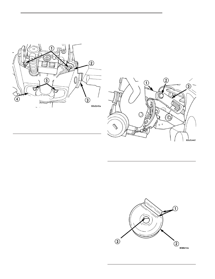
(32) Remove the 2 steering column upper mount-

ing bracket to support bracket nuts (Fig. 27). Then
loosen the 2 bolts attaching the steering column
lower mounting bracket to support bracket (Fig. 27).

(33) Remove the steering column from the support

bracket by pulling it rearward, then out of the car.

INSTALLATION - STEERING COLUMN

(1) Install the steering column on the steering col-

umn support bracket. Loosely install the two steering
column attaching nuts.

(2) Loosely tighten the two steering column upper

mounting nuts (Fig. 27) to hold the steering column
in place. Center the steering column in place, side to
side, then install the two lower mounting bolts (Fig.
27). Then equally tighten both steering column upper
mounting nuts until upper steering column mounting
bracket is seated against support bracket. Tighten
the four steering column bracket to support bracket
fasteners to 12 N·m (105 in. lbs.), tightening the
upper mounting nuts first, then the lower mounting
bolts.

(3) Assemble the intermediate steering shaft to the

steering column flex coupler (Fig. 26). Tighten the
coupler pinch bolt nut to a torque of 27 N·m (240 in.
lbs.). Be sure to install steering coupler pinch bolt
retaining pin.

(4) Install the two air ducts under the steering col-

umn (Fig. 25).

(5) If the vehicle is equipped with a floor shifter,

install the shifter/ignition interlock cable (Fig. 20) in
the lock cylinder housing.

(6) Install the shift cable mounting bracket (Fig.

24) on the steering column. The shift cable mounting
bracket is mounted to the steering column by the two
mounting screws.

(7) If the vehicle is equipped with a steering column

mounted shift lever, first verify that the shift lever is
locked in the park position. Then, install the shift cable
on the shifter mechanism (Fig. 28). The shift cable must
be fully inserted onto the pin of the shifter mechanism.

(8) If the vehicle is equipped with a steering col-

umn mounted shift lever, install the brake transmis-
sion interlock solenoid on the shift lever mechanism.
To do so, perform the following:

(a) Align the flat inside the solenoid (Fig. 29)

with the flat on the shift lever mounting stud.

Fig. 29 Flat Inside BTSI Solenoid

1 - GUIDES
2 - SOLENOID
3 - FLAT

Fig. 27 Steering Column Mounting

1 - MOUNTING NUTS
2 - STEERING COLUMN UPPER MOUNTING BRACKET
3 - STEERING COLUMN SUPPORT BRACKET
4 - STEERING COLUMN LOWER MOUNTING BRACKET
5 - MOUNTING BOLTS

Fig. 28 Installed Shift Cable

1 - SHIFTER MECHANISM
2 - PIN
3 - SHIFT CABLE

LH

COLUMN

19 - 21

COLUMN (Continued)

(b) Slide the solenoid completely onto the shift

lever mounting stud aligning the plastic guide
formed into the solenoid housing with the flange on
the shift lever mechanism bracket (Fig. 30).

(c) Install the retainer clip until it snaps into

place in the slot cut into the shift lever mounting
stud (Fig. 31).

(d) Verify the solenoid is locked in place and will

not slide off the mounting stud.

(e) Connect the wiring harness connector to the

solenoid.

(9) Install the ignition switch on the steering col-

umn. Install and securely tighten the 2 screws (Fig.
19) mounting the ignition switch to the steering col-
umn.

(10) If the vehicle is equipped with a steering col-

umn mounted shift lever and if a new ignition shift
interlock cassette has been installed, the interlock
system must be adjusted. Adjust the interlock system
by pushing in on the adjustment tab until it stops
(Fig. 32). The adjustment tab will click as it moves
into position. Ensure the tab is fully depressed.

(11) Install the multi-function switch on the steer-

ing column. Install and securely tighten the two
screws (Fig. 18) mounting the multi-function switch
to the steering column. Install the clockspring wiring
harness on the routing clip on the top of the multi-
function switch.

(12) If the vehicle is equipped, clip the SKIM mod-

ule over the key cylinder halo bezel and attach it to
the steering column with its mounting screw. Con-
nect the wiring harness to the module.

(13) Install the clockspring on the steering column.

Install and securely tighten the two screws (Fig. 17)
mounting the clockspring to the steering column.

(14) Install the wiring harness connectors (Fig. 16)

on the clockspring.

(15) If removed, install the trim ring for the key

cylinder on the lock cylinder housing.

(16) Install the lower shroud (Fig. 15) on the steer-

ing column. Install and securely tighten the 2 screws
attaching the lower shroud to the steering column.

(17) Install the tilt lever (Fig. 14) on the steering

column.

(18) Install the upper shroud on the steering col-

umn by snapping it onto the lower shroud.

Fig. 30 Guide And Flange Alignment

1 - BRACKET FLANGE
2 - GUIDE

Fig. 31 Solenoid Retainer Clip Installation

1 - SOLENOID
2 - MOUNTING STUD
3 - RETAINER CLIP

Fig. 32 Ignition Interlock Adjustment Tab

1 - LOCK CYLINDER HOUSING
2 - INTERLOCK CASSETTE
3 - ADJUSTMENT TAB

19 - 22

COLUMN

LH

COLUMN (Continued)

CAUTION: If any doubt is present as to whether the
clockspring is properly centered, This clockspring
centering procedure MUST be performed prior to
installing steering wheel assembly. If clockspring is
not centered it may be overextended, causing
clockspring assembly to become inoperative. The
yellow centering indicator must be present in the
centering window of the clockspring and the arrow
on the clockspring must be pointing at the drive
pin.

(19) Center the clock spring using the following

procedure.

• Depress the plastic locking pin to disengage

clockspring locking mechanism.

• Keeping locking mechanism disengaged, rotate

the clockspring rotor in the CLOCKWISE DIREC-
TION to the end of the travel. Do not apply excessive
torque.

• From the end of clockwise travel, slowly rotate

the rotor in the counterclockwise direction until yel-
low appears in the centering window of clockspring.
When yellow appears in the centering window the
arrow on the clockspring will be pointing at the drive
pin on clock spring rotor.

• Engage the clockspring locking mechanism.

CAUTION: When installing the steering wheel, use
care not to damage the steering wheel finish. The
wood grain on some steering wheels can be easily
marred.

CAUTION: Do not install steering wheel by driving it
onto the shaft. Pull steering wheel down onto steer-
ing column shaft using ONLY the steering wheel
retaining nut.

(20) Feed the clockspring wiring leads through the

steering wheel (Fig. 12). Install steering wheel on
shaft of steering column, making sure the master
serration in the wheel hub and on the steering col-
umn shaft line up.

(21) Install steering wheel to steering column

shaft retaining nut (Fig. 12) and tighten until the
steering wheel is fully installed on the shaft. Tighten
steering wheel retaining nut to a torque of 61 N·m
(45 ft. lbs.).

(22) Turn the key cylinder to the unlock position,

unlocking the steering column shaft.

(23) Connect the horn switch wiring lead from the

clockspring to the driver airbag horn switch wiring
lead (Fig. 11).

(24) Install the airbag electrical lead into connec-

tor on back of driver airbag (Fig. 11). Be sure elec-
trical connector from clockspring is securely
latched into driver airbag connector.

(25) If optional audio control switches are present

on the rear of the steering wheel, connect the 4-way
connector lead from the clockspring to the steering
wheel wiring harness lead. Once connected, place the
connector in back cover formation located at the 12
O’clock position.

CAUTION: The fasteners, screws, and bolts, origi-
nally used for the airbag components are specifi-
cally designed for the airbag system. They must
never be replaced with any substitutes. Anytime a
new fastener is needed, replace only with correct
fasteners provided in service packages or fasteners
listed in the parts book.

NOTE: Make sure steering wheel and airbag module
are in the right-side-up position before installing
airbag module on steering wheel.

(26) Install the airbag module on steering wheel.

Install only the two original or correct replacement
airbag module attaching bolts (Fig. 10). Tighten the
two airbag module attaching bolts to a torque of 8
N·m (75 in. lbs.).

(27) Connect the speed control wiring leads to the

speed control switches.

(28) Install the speed control switches in the steer-

ing wheel (Fig. 9). Install the screws attaching the
speed control switches to the steering wheel. Tighten
the screws to a torque of 1.5 N·m (13 in. lbs.).

(29) Install the diagnostic connector on the rein-

forcement (Fig. 8).

(30) Install the reinforcement on the instrument

panel (Fig. 7). Install the four bolts mounting the
reinforcement to the instrument panel.

(31) Install the parking brake release cable on the

parking brake release handle in the lower instru-
ment panel cover (Fig. 6).

(32) Install the wiring harness connector on the

trunk release switch in the lower instrument panel
cover (Fig. 5).

(33) Install the lower instrument panel cover.
(34) Install the two screws behind the fuse panel

cover attaching the lower instrument panel cover to
the instrument panel (Fig. 4).

(35) Install the fuse panel cover on the left end of

the instrument panel (Fig. 3).

CAUTION: When reconnecting the battery terminals
on a vehicle that has had the airbag module
removed, ensure that no occupants are in the vehi-
cle, then perform the following procedure.

(36) Using the following procedure, reconnect the

remote ground cable on the shock tower ground stud.

LH

COLUMN

19 - 23

COLUMN (Continued)

• Connect DRBIIIt scan tool to diagnostic connec-

tor below the column.

• Turn ignition key to ON position. Exit vehicle

with the DRBIII

t scan tool.

• Ensuring that there are no occupants in the vehicle,

connect negative cable to negative post of the battery.

• Using the DRBIIIt scan tool, read and record

active fault codes. Also read and record any stored
fault codes. Refer to Appropriate Body Diagnostic
Information if any faults are found.

• Erase stored faults if there are no active fault

codes. If problems remain, fault codes will not erase.

• From the passenger side of the vehicle, turn

ignition key to OFF and then ON observing instru-
ment cluster airbag lamp. It should go on for six to
eight seconds, then go out. This will indicate that the
airbag system is functioning normally.

• If airbag warning lamp fails to light, blinks on and

off or goes on and stays on, there is an airbag system
malfunction. Refer to Appropriate Body Diagnostic
Information to diagnose the system malfunction.

(37) Test the operation of the horn, lights and any

other functions that are steering column operated. If
applicable, reset the radio and the clock.

(38) Road test vehicle to ensure proper operation

of the steering system and the speed control system.

IGNITION SWITCH

REMOVAL

The ignition switch attaches to the lock cylinder

housing on the end opposite the lock cylinder. For
ignition switch terminal and circuit identification,
refer to the Wiring Diagrams section.

(1) Disconnect negative cable from battery.
(2) Remove tilt lever attaching screw. Remove lever.
(3) Remove upper and lower cover from steering

column.

(4) Remove Sentry Key Immobilizer Module (SKIM)

if equipped. Refer to the Power Door Locks section for
removal.

(5) Remove multi-function switch.
(6) Disconnect electrical connector from ignition

switch (Fig. 33).

(7) Remove

Ignition

switch

mounting

screws.

Remove switch.

INSTALLATION

The ignition switch attaches to the lock cylinder

housing on the end opposite the lock cylinder. For
ignition switch terminal and circuit identification,
refer to the Wiring Diagrams section.

(1) A tab on the ignition switch indexes to a notch

in the lock cylinder housing (Fig. 34). Also, a slot in
the end of the ignition switch fits over the shaft in

the end of the lock cylinder housing. Use the ignition
key to rotate the lock cylinder to align the ignition
switch with lock cylinder housing.

(2) Install and tighten ignition switch mounting

screws.

(3) Attach electrical connector to ignition switch.
(4) Install multi-function switch.
(5) Install SKIM if equipped, refer to the Power

Door Locks section for installation.

(6) Install upper and lower cover on steering col-

umn.

(7) Install tilt lever.
(8) Connect negative cable to battery.

Fig. 33 Ignition Switch Removal/Installation

1 - STEERING COLUMN
2 - IGNITION SWITCH

Fig. 34 Ignition Switch Alignment

1 - IGNITION SWITCH
2 - TAB
3 - NOTCH
4 - SHAFT

19 - 24

COLUMN

LH

COLUMN (Continued)


Content   ..  280  281  282  283   ..