Chrysler 300M, Dodge Interpid. Manual - part 280


  Index      Chrysler     Chrysler 300M / Concorde / Interpid / LHS, Dodge Interpid - service repair manual 2000-2004 year


Search            


Content   ..  278  279  280  281   ..


Chrysler 300M, Dodge Interpid. Manual - part 280


WARNING: THE AIR BAG SYSTEM IS A SENSITIVE,
COMPLEX ELECTRO-MECHANICAL UNIT. BEFORE
ATTEMPTING TO DIAGNOSE, REMOVE OR INSTALL
THE AIR BAG SYSTEM COMPONENTS YOU MUST
FIRST DISCONNECT AND ISOLATE THE BATTERY
NEGATIVE (GROUND) CABLE. FAILURE TO DO SO
COULD RESULT IN ACCIDENTAL DEPLOYMENT OF
THE AIR BAG AND POSSIBLE PERSONAL INJURY.
THE FASTENERS, SCREWS, AND BOLTS, ORIGI-
NALLY USED FOR THE AIR BAG COMPONENTS,
HAVE SPECIAL COATINGS AND ARE SPECIFI-
CALLY DESIGNED FOR THE AIR BAG SYSTEM.
THEY MUST NEVER BE REPLACED WITH ANY SUB-
STITUTES.

ANYTIME

A

NEW

FASTENER

IS

NEEDED, REPLACE WITH THE CORRECT FASTEN-
ERS PROVIDED IN THE SERVICE PACKAGE OR
FASTENERS

LISTED

IN

THE

PARTS

BOOKS.

BEFORE

SERVICING

A

STEERING

COLUMN

EQUIPPED WITH AN AIR BAG, (Refer to 8 - ELEC-
TRICAL/RESTRAINTS - WARNING)

WARNING: WHEN HANDLING AN UNDEPLOYED
AIRBAG MODULE DURING SERVICING OF THE
STEERING COLUMN THE FOLLOWING PRECAU-
TIONS

SHOULD

BE

OBSERVED. AT

NO

TIME

SHOULD ANY SOURCE OF ELECTRICITY BE PER-
MITTED NEAR THE INFLATOR ON THE BACK OF
THE AIRBAG MODULE. WHEN CARRYING A LIVE
MODULE, THE TRIM COVER SHOULD BE POINTED
AWAY FROM THE BODY TO MINIMIZE INJURY IF
MODULE ACCIDENTLY DEPLOYS. IF AIRBAG MOD-
ULE IS PLACED ON A BENCH OR OTHER SUR-
FACE, PLASTIC COVER SHOULD BE FACE UP TO
MINIMIZE MOVEMENT IN CASE OF ACCIDENTAL
DEPLOYMENT.

WARNING: SAFETY GOGGLES SHOULD BE WORN
AT ALL TIMES WHEN WORKING ON STEERING
COLUMNS.

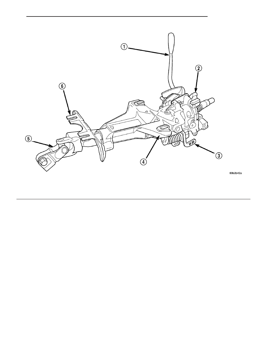
Fig. 1 Steering Column

1 - SHIFT LEVER (COLUMN SHIFT ONLY)
2 - TILT HOUSING
3 - TILT MECHANISM ACTUATOR

4 - STEERING COLUMN MOUNTING BRACKET
5 - STEERING COLUMN COUPLER
6 - STEERING COLUMN LOWER MOUNTING BRACKET

LH

COLUMN

19 - 13

COLUMN (Continued)

CAUTION

CAUTIONS

CAUTION: Disconnect the negative (ground) cable
from the battery, before servicing any column com-
ponent.

CAUTION: Do not attempt to remove the pivot pins
to disassemble the tilting mechanism. Damage will
occur.

DIAGNOSIS AND TESTING - STEERING
COLUMN

For diagnosis of conditions relating to the steering

column, refer to the steering system diagnosis charts
at the beginning of Steering.

The steering column MUST be replaced whenever

any of the following conditions exist:

• Whenever a vehicle is involved in a collision

which deploys the air bag, regardless of the extent of
damage done to the vehicle.

• If a vehicle is involved in an impact of the vehi-

cle’s front suspension or undercarriage, which results
in any type of damage to the front suspension cross-
member.

• Under any conditions which result in the steer-

ing column assembly or steering column shaft receiv-
ing a force great enough to move the steering column
or shaft forward or rearward in the vehicle.

REMOVAL - STEERING COLUMN

NOTE: This procedure is to be used when replacing
the steering column. It is written to reflect that
objective. If the column is to be removed as one
assembly, or without removing the steering wheel,
the steering wheel must be turned from the straight
ahead position to the RIGHT 180° and locked in
place. Lock the column in this position by removing
the key from the key cylinder. This MUST be per-
formed before the steering coupler to the gear is
disconnected. This is done to prevent the chance of
damaging the clockspring. When reconnecting the
steering coupler to the intermediate shaft, verify the
front wheels have not moved from their position
when column was removed. If during column rein-
stallation, any doubt is present as to whether the
clockspring is properly centered, the clockspring
centering procedure in Installation Step Step 19
MUST be performed prior to connecting the steer-
ing coupler.

(1) Remove remote ground cable from ground stud

on shock tower and isolate ground cable from vehicle
by installing isolator on stud (Fig. 2).

(2) Remove the fuse panel cover from the left end

of the instrument panel (Fig. 3).

Fig. 2 Correctly Isolated Remote Ground Cable

1 - CABLE ISOLATOR
2 - GROUND STUD
3 - GROUND CABLE

Fig. 3 Fuse Panel Cover

1 - FUSE PANEL COVER
2 - INSTRUMENT PANEL

19 - 14

COLUMN

LH

COLUMN (Continued)

(3) Remove the 2 screws behind the fuse panel

cover attaching the lower instrument panel cover to
the instrument panel (Fig. 4).

(4) Remove the lower instrument panel cover. The

lower instrument panel cover is attached by retain-
ing clips along the top and right edge.

(5) Remove the wiring harness connector from the

trunk release switch in the lower instrument panel
cover (Fig. 5).

(6) Remove the parking brake release cable, from

the park brake release handle in the lower instru-
ment panel cover (Fig. 6).

(7) Remove the 4 bolts (Fig. 7) mounting the rein-

forcement (Fig. 7) to the instrument panel. Remove the
reinforcement from the instrument panel. Remove the
diagnostic connector (Fig. 8) from the reinforcement.

Fig. 4 Lower Instrument Panel Cover Mounting Screws

1 - MOUNTING SCREWS
2 - INSTRUMENT PANEL BRACKET
3 - LOWER INSTRUMENT PANEL COVER

Fig. 5 Trunk Release Wiring

1 - WIRING HARNESS CONNECTOR
2 - TRUNK RELEASE SWITCH
3 - LOWER INSTRUMENT PANEL COVER

Fig. 6 Park Brake Release Cable

1 - PARK BRAKE RELEASE CABLE
2 - PARK BRAKE RELEASE HANDLE
3 - LOWER INSTRUMENT PANEL COVER

Fig. 7 Reinforcement Panel

1 - REINFORCEMENT PANEL
2 - MOUNTING BOLTS

Fig. 8 Diagnostic Connector

1 - DIAGNOSTIC CONNECTOR
2 - REINFORCEMENT PANEL

LH

COLUMN

19 - 15

COLUMN (Continued)

(8) Before beginning removal of steering column

assembly from vehicle, be sure front wheels of vehicle
are in the STRAIGHT-AHEAD position.

CAUTION: When removing the steering wheel, use
care not to damage the steering wheel finish. The
wood grain on some steering wheels can be easily
marred.

(9) Remove the speed control switches (Fig. 9)

from the steering wheel. The speed control switches
are mounted to the steering wheel by two screws
(one screw, each switch) which are accessible from
the back side of the steering wheel. Disconnect the
wire connector from each switch.

WARNING: WHEN AN UNDEPLOYED AIRBAG IS TO
BE REMOVED FROM THE STEERING WHEEL, DIS-
CONNECT BATTERY GROUND CABLE AND ISO-
LATE.

ALLOW

SYSTEM

CAPACITOR

TO

DISCHARGE FOR TWO MINUTES, THEN BEGIN AIR-
BAG REMOVAL.

WARNING: WHEN HANDLING AN UNDEPLOYED
AIRBAG DURING SERVICE OF THE STEERING COL-
UMN, THE FOLLOWING PRECAUTIONS SHOULD
BE

OBSERVED.

AT

NO

TIME

SHOULD

ANY

SOURCE OF ELECTRICITY BE PERMITTED NEAR
THE INFLATOR ON THE BACK OF THE AIRBAG
MODULE. WHEN CARRYING A LIVE MODULE, THE
TRIM COVER SHOULD BE POINTED AWAY FROM
THE BODY TO MINIMIZE INJURY IF MODULE ACCI-
DENTLY DEPLOYS. IF AIRBAG MODULE IS PLACED
ON A BENCH OR OTHER SURFACE, PLASTIC
COVER SHOULD BE FACE UP TO MINIMIZE MOVE-
MENT IN CASE OF ACCIDENTAL DEPLOYMENT.

(10) Remove the 2 bolts attaching the driver air-

bag to the steering wheel (Fig. 10).

(11) Remove the driver airbag from the steering

wheel.

(12) Disconnect the electrical connector from the

back of the airbag (Fig. 11). Connector is removed by
pulling it straight out of the airbag. Do not twist the
connector when removing it from the airbag.

(13) Remove the horn switch wire from the clock-

spring horn wire (Fig. 11).

(14) If optional audio control switches are present

on the rear of the steering wheel, disconnect the
4-way connector between the clockspring and steer-
ing wheel wiring harness.

Fig. 9 Speed Control Switches

1 - STEERING WHEEL
2 - SPEED CONTROL SWITCHES

Fig. 10 Driver Airbag Attaching Bolts

1 - DRIVER AIRBAG
2 - STEERING WHEEL
3 - MOUNTING SCREWS

Fig. 11 Driver Airbag Electrical Connections

1 - STEERING WHEEL
2 - HORN SWITCH WIRE
3 - DRIVER AIRBAG
4 - CONNECTOR LOCK
5 - AIRBAG ELECTRICAL CONNECTOR

19 - 16

COLUMN

LH

COLUMN (Continued)


Content   ..  278  279  280  281   ..