Chrysler 300M, Dodge Interpid. Manual - part 256


  Index      Chrysler     Chrysler 300M / Concorde / Interpid / LHS, Dodge Interpid - service repair manual 2000-2004 year


Search            


Content   ..  254  255  256  257   ..


Chrysler 300M, Dodge Interpid. Manual - part 256


DIAGNOSIS AND TESTING - INTAKE
MANIFOLD LEAKS

An intake manifold air leak is characterized by

lower than normal manifold vacuum. Also, one or
more cylinders may not be functioning.

WARNING: USE EXTREME CAUTION WHEN THE
ENGINE IS OPERATING. DO NOT STAND IN A
DIRECT LINE WITH THE FAN. DO NOT PUT YOUR
HANDS NEAR THE PULLEYS, BELTS OR THE FAN.
DO NOT WEAR LOOSE CLOTHING.

(1) Start the engine.
(2) Spray a small stream of water (Spray Bottle) at

the suspected leak area.

(3) If engine RPM’S change, the area of the sus-

pected leak has been found.

(4) Repair as required.

INTAKE MANIFOLD - UPPER

REMOVAL

(1) Disconnect negative cable from remote jumper

terminal.

(2) Disconnect the Inlet Air Temperature (IAT)

Sensor connector. Remove air cleaner housing and
inlet hose (Fig. 121).

(3) Remove throttle and speed control cables from

throttle arm and bracket (Refer to 14 - FUEL SYS-
TEM/FUEL

INJECTION/THROTTLE

CONTROL

CABLE - REMOVAL).

(4) Disconnect electrical connectors from the fol-

lowing sensors and actuators:

• Short Runner Valve (SRV)(If Equipped)

• Manifold Tuning Valve (MTV)(If Equipped)

• Throttle Position Sensor (TPS)

• Idle Air Control (IAC)

• Manifold Absolute Pressure (MAP)

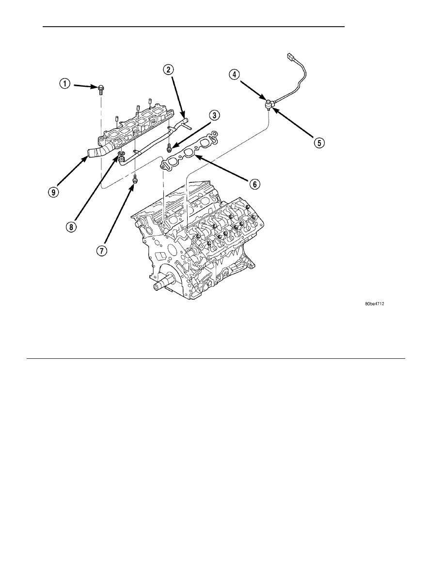
Fig. 120 LOWER INTAKE MANIFOLD

1 - BOLT

6 - GASKET

2 - HEATER SUPPLY TUBE

7 - BOLT

3 - BOLT

8 - O-RING

4 - BOLT

9 - INTAKE MANIFOLD-LOWER

5 - KNOCK SENSOR

LH

ENGINE

9 - 71

INTAKE MANIFOLD (Continued)

(5) Disconnect vacuum hoses from the following:
• Speed Control Reservoir

• Positive Crankcase Ventilation (PCV) Valve

• Proportional Purge Solenoid

• Power Brake Booster
(6) Remove right side (Fig. 122) and left side (Fig.

123) intake manifold supports.

(7) Remove support brackets at intake manifold

front corners and at MTV (Fig. 124).

(8) Loosen upper fastener attaching throttle body

to support bracket.

(9) Remove bolts attaching intake manifold and

remove manifold (Fig. 125).

Fig. 121 AIR CLEANER WITH INLET HOSE

1 - AIR CLEANER ASSEMBLY WITH AIR INLET HOSE
2 - THROTTLE BODY

Fig. 122 INTAKE MANIFOLD SUPPORT - RIGHT

1 - SUPPORT BRACKET

Fig. 123 INTAKE MANIFOLD SUPPORT - LEFT

1 - SUPPORT BRACKET

Fig. 124 INTAKE MANIFOLD SUPPORTS - FRONT

1 - SUPPORT BRACKETS

9 - 72

ENGINE

LH

INTAKE MANIFOLD - UPPER (Continued)

INSPECTION

Check manifold for:
• Damage and cracks

• Gasket surface damage or warpage

• Damaged or clogged EGR ports
If the manifold exihibits any damaged or warped

conditions, replace the manifold. Clean EGR ports as
neccessary.

INSTALLATION

(1) Clean and inspect gasket sealing surfaces.

NOTE: Intake gaskets can be reused, provided they
are free of cuts or tears.

(2) Inspect gasket for cuts or tears. Replace gas-

kets as necessary.

(3) Install intake manifold (Fig. 125) and hand

start all attaching bolts.

(4) Tighten bolts gradually in sequence shown in

(Fig. 126)until a torque of 12 N·m (105 in. lbs.) is
obtained.

(5) Install right side (Fig. 122) and left side (Fig.

123) intake manifold supports.

(6) Install manifold support brackets at front cor-

ners and at MTV (Fig. 124).

(7) Tighten fastener attaching throttle body to sup-

port bracket.

(8) Connect vacuum lines to the following:
• Speed Control Reservoir

• Positive Crankcase Ventilation (PCV) Valve

• Proportional Purge Solenoid

• Power Brake Booster
(9) Connect electrical connectors to the following:
• Short Runner Valve (SRV)(If Equipped)

• Manifold Tuning Valve (MTV)(If Equipped)

• Throttle Position Sensor (TPS)

• Idle Air Control (IAC)

• Manifold Absolute Pressure (MAP)
(10) Install throttle and speed control cables to

bracket and throttle arm (Refer to 14 - FUEL SYS-
TEM/FUEL

INJECTION/THROTTLE

CONTROL

CABLE - INSTALLATION).

(11) Install air cleaner housing and inlet hose (Fig.

121). Connect Inlet Air Temperature (IAT) Sensor
connector.

(12) Connect negative cable to remote jumper ter-

minal.

Fig. 125 UPPER INTAKE MANIFOLD

1 - INTAKE MANIFOLD-UPPER
2 - BOLT

Fig. 126 UPPER INTAKE MANIFOLD TIGHTENING

LH

ENGINE

9 - 73

INTAKE MANIFOLD - UPPER (Continued)

INTAKE MANIFOLD - LOWER

REMOVAL

(1) Perform fuel pressure release procedure. (Refer

to 14 - FUEL SYSTEM/FUEL DELIVERY - STAN-
DARD PROCEDURE)

(2) Drain the cooling system. (Refer to 7 - COOL-

ING - STANDARD PROCEDURE)

(3) Disconnect the radiator upper hose from the

coolant outlet at front of manifold.

(4) Remove the upper intake manifold. (Refer to 9

-

ENGINE/MANIFOLDS/INTAKE

MANIFOLD

-

REMOVAL)

(5) Disconnect the electrical connectors to fuel

injectors and coolant temperature sensor.

(6) Disconnect heater and coolant bottle supply

hoses from coolant tube at rear of intake manifold
(Fig. 127).

(7) Disconnect the fuel supply hose from fuel rail.

(Refer to 14 - FUEL SYSTEM/FUEL DELIVERY/
FUEL LINES - STANDARD PROCEDURE)

(8) Remove the screw attaching the fuel rail sup-

port bracket to the throttle body support bracket.

(9) Remove the bolts attaching fuel rail.
(10) Remove fuel rail and injectors as an assembly.
(11) Remove bolts attaching lower intake and

remove intake manifold (Fig. 128).

INSPECTION

Check manifold for:
• Damage and cracks

• Gasket surface damage or warpage

• Damaged fuel injector ports
If the manifold exihibits any of these conditions,

replace the manifold.

INSTALLATION

(1) Clean all sealing surfaces.

NOTE: Gaskets can be reused provided they are
free of tears or cuts.

(2) Inspect gaskets for tears or cuts. Replace as

necessary.

(3) Position gaskets and intake manifold on cylin-

der head surfaces.

(4) Install fuel rail with injectors.
(5) Install intake manifold bolts and gradually

tighten in sequence shown in (Fig. 129) until a
torque of 28 N·m (250 in. lbs.) is obtained.

(6) Install

screw

attaching

fuel

rail

support

bracket to the throttle body support bracket.

(7) Connect fuel supply hose to fuel rail. (Refer to

14 - FUEL SYSTEM/FUEL DELIVERY/FUEL LINES
- STANDARD PROCEDURE)

(8) Connect heater and coolant bottle supply hoses

to coolant tube at rear of intake manifold (Fig. 127).

(9) Connect electrical connectors to fuel injectors

and coolant temperature sensor.

(10) Install the upper intake manifold. (Refer to 9 -

ENGINE/MANIFOLDS/INTAKE

MANIFOLD

-

INSTALLATION)

(11) Connect the radiator upper hose to the coolant

outlet at front of lower manifold.

(12) Fill the cooling system. (Refer to 7 - COOL-

ING - STANDARD PROCEDURE)

Fig. 127 HEATER SUPPLY HOSE CONNECTIONS

1 - HEATER SUPPLY HOSE
2 - COOLANT BOTTLE SUPPLY HOSE

9 - 74

ENGINE

LH


Content   ..  254  255  256  257   ..