Chrysler 300M, Dodge Interpid. Manual - part 104


  Index      Chrysler     Chrysler 300M / Concorde / Interpid / LHS, Dodge Interpid - service repair manual 2000-2004 year


Search            


Content   ..  102  103  104  105   ..


Chrysler 300M, Dodge Interpid. Manual - part 104


POWER SEAT TRACK

DESCRIPTION

The eight/four-way power seat options include a

single electrically operated power seat track located
under each front bucket seat. The power seat track
unit replaces the standard equipment manual seat
tracks. The lower half of the power seat track is
secured at the front with two bolts to the floor panel
seat cross member, and at the rear with two bolts to
the floor panel. Four nuts secure the bottom of the
seat cushion frame to four studs on the upper half of
the power seat track unit.

The power seat track unit cannot be repaired, and

is serviced only as a complete unit. If any component
in this unit is faulty or damaged, the entire power
seat track unit must be replaced.

OPERATION

The power seat track unit includes two/three

reversible electric motors that are secured to the
upper half of the track unit. Each motor moves the
seat adjuster through a combination of worm-drive
gearboxes and screw-type drive units. Each of the
driver side power seat track motors used on models
equipped with the optional memory system, also has
a position potentiometer integral to the motor assem-
bly, which electronically monitors the motor position.

The front and rear (if equipped) of the seat are

operated by two separate vertical adjustment motors.
These motors can be operated independently of each
other, tilting the entire seat assembly forward or
rearward; or, they can be operated in unison by
selecting the proper power seat switch functions,
which will raise or lower the entire seat assembly.
The third motor is the horizontal adjustment motor,
which moves the seat track in the forward and rear-
ward directions.

DIAGNOSIS AND TESTING - POWER SEAT
TRACK

(1) Remove power seat switch from seat. Refer to

the procedure in this section.

(2) Disconnect wire harness connector.
(3) Check Pin 1 for battery voltage and Pin 5 for

ground.

(4)

To test the seat motors and verify proper seat

responses, refer to (Fig. 9) and the Seat Motor Test
table. Using two jumper wires, connect one to a bat-
tery supply and the second to a ground. Connect the
other ends to the seat wire harness connector as
described in the Seat Motor Test table.

SEAT TRACK MOTOR TEST

SEAT CONNECTOR

CONNECT JUMPER

SEAT ACTION

B (+)

B (-)

DRIVER
SIDE

PASSENGER
SIDE

PIN 9

PIN 6

FRONT
RISER UP

FRONT
RISER
DOWN

PIN 6

PIN 9

FRONT
RISER
DOWN

FRONT
RISER UP

PIN 10

PIN 3

FORWARD

FORWARD

PIN 3

PIN 10

REARWARD

REARWARD

PIN 8

PIN 7

REAR
RISER UP

REAR RISER
DOWN (IF
EQUIP.)

PIN 7

PIN 8

REAR
RISER
DOWN

REAR RISER
UP (IF
EQUIP.)

PIN 4

PIN 2

RECLINER
UP

RECLINER
UP

PIN 2

PIN 4

RECLINER
DOWN

RECLINER
DOWN

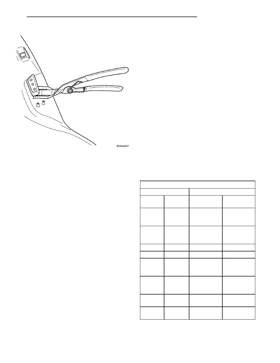
Fig. 8 Removing Switch Control Knobs - Typical

LH

POWER SEATS

8N - 19

PASSENGER POWER SEAT SWITCH (Continued)

REMOVAL

WARNING: SOME VEHICLES ARE EQUIPPED WITH
SEATBACK

MOUNTED

AIRBAGS.

BEFORE

ATTEMPTING TO DIAGNOSE OR SERVICE ANY
SEAT OR POWER SEAT SYSTEM COMPONENT
YOU MUST FIRST DISCONNECT AND ISOLATE THE
BATTERY NEGATIVE CABLE. THEN WAIT TWO MIN-
UTES FOR THE SYSTEM CAPACITOR TO DIS-
CHARGE BEFORE FURTHER SYSTEM SERVICE.
THIS IS THE ONLY SURE WAY TO DISABLE THE
AIRBAG SYSTEM. FAILURE TO DO SO COULD
RESULT IN ACCIDENTAL AIRBAG DEPLOYMENT
AND POSSIBLE PERSONAL INJURY.

(1) Remove the appropriate front seat from the

vehicle. Refer to the Body section for the procedure.

(2) Remove two seat back mounting bolts and also

remove two seat back recliner bolts (Fig. 10).

(3) Remove four seat track mounting bolts from

cushion pan.

(4) Remove the seat track from seat.

INSTALLATION

(1) Position the seat track and install the retaining

bolts in the seat cushion pan. Torque the bolts to
45-60 N·m.

(2) Install the two seat back mounting bolts.

Torque the bolts to 45-60 N·m.

(3) Install the two seat back recliner bolts. Torque

the bolts to 45-60 N·m.

(4) Install the seat in the vehicle. Refer to the

Body section of the service manual for the procedure.

Fig. 9 Power Seat Wire Harness Pin Call-Out

1 - BLUE
2 - VIEWED FROM BODY HARNESS END

Fig. 10 Seat Track Removal

1 - TRACK TO SEAT CUSHION BOLTS
2 - FRONT
3 - SEAT BACK RECLINER BOLTS
4 - VIEWED FROM TOP OF TRACK

8N - 20

POWER SEATS

LH

POWER SEAT TRACK (Continued)

POWER WINDOWS

TABLE OF CONTENTS

page

page

POWER WINDOWS

DESCRIPTION

. . . . . . . . . . . . . . . . . . . . . . . . . 21

OPERATION

. . . . . . . . . . . . . . . . . . . . . . . . . . . 21

DIAGNOSIS AND TESTING - POWER

WINDOWS

. . . . . . . . . . . . . . . . . . . . . . . . . . . 21

WINDOW MOTOR

REMOVAL

. . . . . . . . . . . . . . . . . . . . . . . . . . . . . 22

INSTALLATION

. . . . . . . . . . . . . . . . . . . . . . . . . 22

WINDOW SWITCH

DIAGNOSIS AND TESTING - WINDOW

SWITCH

. . . . . . . . . . . . . . . . . . . . . . . . . . . . 23

REMOVAL

. . . . . . . . . . . . . . . . . . . . . . . . . . . . . 23

INSTALLATION

. . . . . . . . . . . . . . . . . . . . . . . . . 24

POWER WINDOWS

DESCRIPTION

The power window system allows each of the door

windows to be raised and lowered electrically by
actuating a switch on the trim panel of each respec-
tive door. A master switch on the driver side front
door trim panel allows the driver to raise or lower
each of the passenger door windows, and to lock out
the individual switches on the passenger doors from
operation. On police vehicles, the rear window
switches are inoperable. The power window system
receives battery feed through a circuit breaker in the
junction block, only when the ignition switch is in
the On position.

The power window system includes the power win-

dow switches on each door trim panel, the circuit
breaker in the junction block, and the power window
motors inside each door. For service of mechanical
components, (Refer to 23 - BODY/DOOR - FRONT/
WINDOW REGULATOR - REMOVAL) or (Refer to
23 - BODY/DOORS - REAR - REMOVAL).

OPERATION

Front and rear door window lift motors are of the

permanent magnet type. A battery positive and neg-
ative connection to either of the two motor terminals
will cause the motor to rotate in one direction.
Reversing current through these same two connec-
tions will cause the motor to rotate in the opposite
direction.

Each individual motor is grounded through the

master switch.

DIAGNOSIS AND TESTING - POWER
WINDOWS

WIRING VOLTAGE TEST

The following circuit test sequence determines

whether or not voltage is continuous through the
body harness to switch.

(1) Remove the driver door trim panel. (Refer to 23

- BODY/DOOR - FRONT/TRIM PANEL - REMOVAL)
for proper procedures.

(2) Carefully separate wiring harness connector

from switch body.

(3) Using a voltmeter, connect the ground lead to

the Pin 10 of the wiring harness connector.

(4) Using the positive lead, check Pin 1 of the har-

ness connector for battery voltage. If OK, go to Win-
dow Switch Test below. If not OK, check 20 amp
circuit breaker in the Junction Block, if the circuit
breaker is OK, repair wire as necessary. For wiring,
specific connector type and location, refer to the
appropriate wiring information. The wiring informa-
tion includes wiring diagrams, proper wire and con-
nector repair procedures, details of wire harness
routing and retention, connector pin-out information
and location views for the various wire harness con-
nectors, splices and grounds.

POWER WINDOW MOTOR TEST

(1) Remove door trim panel, (Refer to 23 - BODY/

DOOR - FRONT/TRIM PANEL - REMOVAL) or
(Refer to 23 - BODY/DOORS - REAR/TRIM PANEL -
REMOVAL).

(2) Connect positive (+) lead from a test battery to

either of the two motor terminals.

LH

POWER WINDOWS

8N - 21

(3) Connect negative (-) lead from test battery to

remaining motor terminal.

(4) The motor should now rotate in one direction to

either move window up or down.

(a) If window happens to already be in full UP

position and motor is connected so as to move it in
UP direction no movement will be observed.

(b) Likewise, motor connected to move window

in DOWN direction no movement will be observed
if window is already in full DOWN position.

(c)

Reverse battery leads in Step 1 and Step 2

and window should now move. If window does not
move, remove motor. (Refer to 8 - ELECTRICAL/
POWER WINDOWS/WINDOW MOTOR - REMOV-
AL).
(5) If window moved completely up or down, the

test leads should be reversed one more time to com-
plete a full window travel inspection.

(6) If window does not move, check to make sure

that it is free.

(7) It is necessary that the window be free to slide

up and down in the glass channels. If the window is
not free to move up and down, the window lift motor
will not be able to move the glass.

(8) To determine if the glass is free is to disconnect

the regulator from the glass lift plate. Remove the
two attaching screws, and slide the window up and
down by hand.

WINDOW MOTOR

REMOVAL

(1) Move the window to the full-up position, if pos-

sible.

(2) Open hood and disconnect the negative battery

cable remote terminal from the remote battery post.

(3) Remove door trim panel. (Refer to 23 - BODY/

DOOR - FRONT/TRIM PANEL - REMOVAL) or
(Refer to 23 - BODY/DOORS - REAR/TRIM PANEL -
REMOVAL).

(4) Remove window regulator. (Refer to 23 -

BODY/DOOR - FRONT/WINDOW REGULATOR -
REMOVAL) or (Refer to 23 - BODY/DOORS - REAR -
REMOVAL).

WARNING:
FAILURE TO CLAMP THE SECTOR GEAR TO THE
MOUNTING PLATE WHEN REMOVING THE MOTOR
CAN RESULT IN INJURY.

(5) Disconnect wiring connector from motor.
(6) Secure the sector gear and mounting plate with

a C clamp or similar clamping tool. This will prevent
a sudden and forceful movement of the regulator
when the motor is removed.

(7) Remove three mounting screws that hold motor

gearbox to regulator (Fig. 1).

(8) Remove motor from regulator.

INSTALLATION

(1) Install new motor on regulator by positioning

motor gearbox so that it engages regulator sector
teeth.

(2) A slight rotational or rocking movement may

be necessary to bring three motor gearbox screw
holes into proper position.

(3) Install three gearbox screws and one tie down

bracket screw, if applicable. Tighten to 5.6 to 8 N·m
(50 to 70 in. lbs.) torque.

(4) Install regulator. Using the switch, test opera-

tion of motor.

(5) Install trim panel. (Refer to 23 - BODY/DOOR -

FRONT/TRIM PANEL - INSTALLATION) or (Refer
to 23 - BODY/DOORS - REAR/TRIM PANEL -
INSTALLATION).

(6) Connect the negative battery cable remote ter-

minal to the to the remote battery post.

Fig. 1 Motor Removal

1 - CLAMP REGULATOR TO SECTOR GEAR
2 - MOTOR MOUNTING SCREWS

8N - 22

POWER WINDOWS

LH

POWER WINDOWS (Continued)


Content   ..  102  103  104  105   ..