Chrysler 300M, Dodge Interpid. Manual - part 89


  Index      Chrysler     Chrysler 300M / Concorde / Interpid / LHS, Dodge Interpid - service repair manual 2000-2004 year


Search            


Content   ..  87  88  89  90   ..


Chrysler 300M, Dodge Interpid. Manual - part 89


INSTALLATION

(1) Be certain the replacement motor matches the

configuration of the motor removed.

(2) Line up lugs on new motor with the corre-

sponding openings on the headlamp housing making
sure the ball stud on the motor lines up with ball
stud receptacle on the lamp assembly. The receptacle
can be moved by grasping the rubber boot area of the
outboard lamp and moving by hand. Rotate the
motor back into position to secure in place.

(3) Push down on outboard lamp until leveling

motor ball stud snaps into place. Ensure that the ball
stud is fully seated.

(4) Connect the headlamp leveling motor wire con-

nector.

(5) Install the headlamp assembly on the vehicle

(Refer to 8 - ELECTRICAL/LAMPS/LIGHTING -
EXTERIOR/HEADLAMP UNIT - INSTALLATION).

(6) Verify headlamp leveling motor operation.
(7) Check the headlamps for proper alignment.

Align the headlamps if required (Refer to 8 - ELEC-
TRICAL/LAMPS/LIGHTING

-

EXTERIOR/HEAD-

LAMP UNIT - STANDARD PROCEDURE).

NOTE: Headlamps must be aligned with the head-
lamp leveling switch in the “0” position

HEADLAMP LEVELING
SWITCH - EXPORT

DESCRIPTION

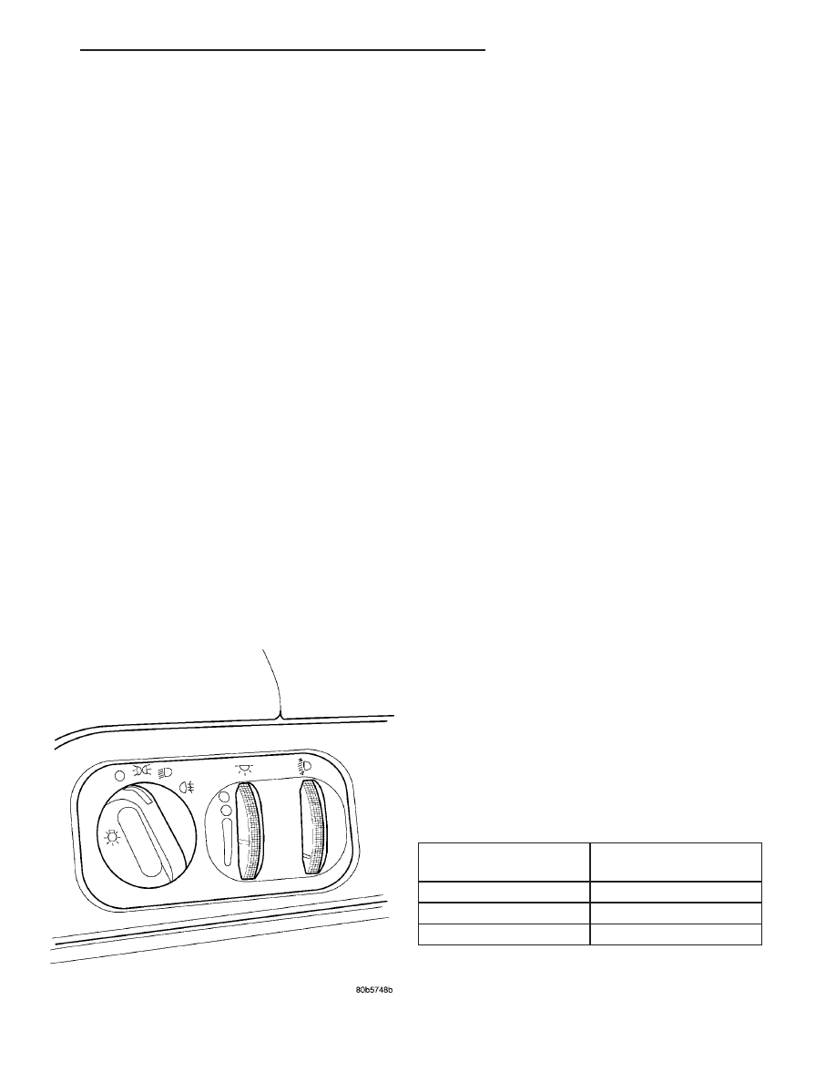
The Headlamp Leveling Switch is located next to

the headlamp switch (Fig. 30) and is the primary
controller of the headlamp leveling system. The lev-
eling switch has three settings 0-2, “0” being the low-
est, “2” being the highest headlight beam vertical
setting.

OPERATION

With the rotation of the headlamp leveling switch

control knob, voltage is adjusted at the headlamp lev-
eling switch (rheostat). This signals the headlamp
leveling

motors

(headlamp

module

mounted)

to

adjust the vertical headlamp beam pattern accord-
ingly. The headlamps must be “ON” in order for the
leveling system to function. Refer to the appropriate
wiring information. The wiring information includes
wiring diagrams, proper wire and connector repair
procedures, details of wire harness routing and
retention, connector pin-out information and location
views for the various wire harness connectors, splices
and grounds.

DIAGNOSIS AND TESTING - HEADLAMP
LEVELING SWITCH - EXPORT

(1) Disconnect and isolate the battery negative

battery cable remote terminal.

(2) Remove the headlamp leveling switch from the

instrument

panel

(Refer

to

8

-

ELECTRICAL/

LAMPS/LIGHTING

-

EXTERIOR/HEADLAMP

SWITCH - REMOVAL).

(3) Disconnect the headlamp leveling switch elec-

trical connector.

(4) Using an Ohm meter and the table below,

check the resistance between the switch connector
pins 1&2.

(5) If the test results are NOT as indicated in the

HEADLAMP LEVELING SWITCH CONTINUITY
table, replace the switch. If the test results ARE as
indicated HEADLAMP LEVELING SWITCH CONTI-
NUITY table, the switch is OK at this time. (Refer to
8 - ELECTRICAL/LAMPS/LIGHTING - EXTERIOR -
DIAGNOSIS AND TESTING).

HEADLAMP LEVELING SWITCH CONTINUITY

SWITCH POSITION

RESISTANCE

BETWEEN PINS 1&2

0

0.752

V

1

0.564

V

2

348.8

V

Fig. 30 HEADLAMP LEVELING SWITCH - EXPORT

LH

LAMPS/LIGHTING - EXTERIOR

8L - 25

HEADLAMP LEVELING MOTOR - EXPORT (Continued)

REMOVAL

The headlamp leveling switch is integrated into

the headlamp switch. If the headlamp leveling switch
proves faulty the entire headlamp switch must be
replaced. (Refer to 8 - ELECTRICAL/LAMPS/LIGHT-
ING - EXTERIOR/HEADLAMP SWITCH - REMOV-
AL).

INSTALLATION

The headlamp leveling switch is integrated into

the headlamp switch. If the headlamp leveling switch
proves faulty the entire headlamp switch must be
replaced. (Refer to 8 - ELECTRICAL/LAMPS/LIGHT-
ING - EXTERIOR/HEADLAMP SWITCH - INSTAL-
LATION)

HEADLAMP SWITCH

DESCRIPTION - POLICE

This vehicle is equipped with a stealth mode. Dur-

ing periods of surveillance, the headlamp switch may
be placed in the “A” position or Approach mode (Fig.
31). In this position, all exterior lighting (Daytime
Running Lamps - if equipped) will be cancelled.

NOTE: On Canadian vehicles, the Daytime Running
Lamps will not be disabled. These must stay oper-
able due to Canadian federal regulations.

By pulling out on the switch (toward the driver)

the lamps will be in Apprehend mode (Fig. 31). In
this mode, all M2 circuit interior illumination, except
for PRNDL, odometer, cluster back lighting, and
vehicle critical warning indicators will be cancelled.
The cluster back lighting, PRNDL, and odometer will
go to a minimum dimming level.

The Body Control Module (BCM) must be flashed

with a special police package for the stealth mode to
work. A security provision may require the unique
engine controller to broadcast a code to allow the
BCM to be flashed with the police package program.

OPERATION - POLICE

APPROACH MODE

To

place

the

vehicle’s

lighting

system

into

Approach mode, turn the switch counterclockwise to
the A on the headlamp switch (Fig. 31).

APPREHEND MODE

To place the vehicle’s lighting system into Appre-

hend mode, turn the switch counterclockwise to the A
on the headlamp switch and pull out (toward the
driver) on the selector knob (Fig. 31).

DIAGNOSIS AND TESTING - HEADLAMP
SWITCH

Using an ohmmeter, test for resistance values

between the terminals of the switch as shown in the
HEADLAMP SWITCH RESISTANCE table and (Fig.
32).

HEADLAMP SWITCH RESISTANCE

POSITION

TERMINALS

RESISTANCE

OFF

6 & 12

3600

V

- 5400

V

PARK LAMP ON

6 & 12

44.65

V

- 49.35

V

PARK LAMP
W/FRONT FOG

6 & 12

115

V

± 5%

HEADLAMP ON

6 & 12

209.2

V

- 231

V

HEADLAMP
W/FRONT FOG

6 & 12

690

V

± 5%

AUTO

6 & 12

370.5

V

- 409.5

V

AUTO W/FRONT
FOG

6 & 12

1390

V

± 5%

RHEOSTAT
(THUMBWHEEL)
DIM POSITION

6 & 3

180

V

- 1870

V

(POT)

RHEOSTAT
(THUMBWHEEL)
BRIGHT
POSITION
(FUNERAL
MODE)

6 & 3

2280

V

- 2520

V

DOME LAMP

6 & 3

3230

V

- 3570

V

Fig. 31 HEADLAMP SWITCH - POLICE

1 - APPROACH MODE (APPREHEND MODE - PULLED OUT)
2 - OFF
3 - HEADLAMPS
4 - PARKING LAMPS

8L - 26

LAMPS/LIGHTING - EXTERIOR

LH

HEADLAMP LEVELING SWITCH - EXPORT (Continued)

REMOVAL

(1) Open hood and disconnect the negative battery

cable remote terminal from the remote battery post.

(2) Remove the left end cover, left instrument

panel trim cover, and the cluster bezel. Refer to the
various Removal and Installation procedures in this
section.

(3) Remove the three screws retaining headlamp

switch to cluster bezel.

(4) Remove headlamp switch from bezel.
(5) Twist out lamp sockets are serviceable at this

time. Ensure that the switch is seated against the
pad.

INSTALLATION

(1) Install the headlamp switch into bezel.
(2) Install the three screws retaining headlamp

switch to cluster bezel.

(3) Install the left end cover, left instrument panel

trim cover, and the cluster bezel. Refer to Instrument
Panel, Removal and Installation.

(4) Connect the negative battery cable remote ter-

minal to the remote battery post.

HEADLAMP UNIT

STANDARD PROCEDURE

STANDARD PROCEDURE - HEADLAMP UNIT
ALIGNMENT

HEADLAMP UNIT ALIGNMENT PREPARATION

The vehicle headlamp units are equipped with a

bubble level to aid up/down headlamp unit align-
ment. The bubble level is used to assist headlamp
unit alignment when compensating for vehicle ride
height changes due to heavy luggage compartment

loads or vehicle ride height changes. The vehicle
should always be on a level surface when headlamp
unit alignments are checked or changed. Headlamp
unit alignment should always be first attempted by
using the bubble level.

The bubble levels cannot be calibrated. The bubble

level adjustments are set by the manufacturer. Hori-
zontal alignment does not ordinarily have to be
changed except in the case of body damage or tam-
pering.

(1) Verify headlamp dimmer switch and high beam

indicator operation.

(2) Inspect and correct damaged or defective com-

ponents that could interfere with proper headlamp
alignment.

(3) Verify proper tire inflation.
(4) Clean headlamp lenses.
(5) Verify that luggage area is not heavily loaded.
(6) Fuel tank should be FULL. Add 2.94 kg (6.5

lbs.) of weight over the fuel tank for each estimated
gallon of missing fuel.

ALIGNMENT SCREEN PREPARATION

(1) Position vehicle on a level surface perpendicu-

lar to a flat wall 7.62 meters (25 ft.) away from front
of headlamp lens.

(2) If necessary, tape a line on the floor 7.62

meters (25 ft.) away from and parallel to the wall.

(3) From the floor up 1.27 meters (5 ft.), tape a

line on the wall at the center line of the vehicle.
Sight along the center line of the vehicle (from rear
of vehicle forward) to verify accuracy of the line
placement.

(4) Rock vehicle side-to-side three times to allow

suspension to stabilize.

(5) Jounce front suspension three times by pushing

downward on front bumper and releasing.

(6) Measure the distance from the center of the

headlamp bulbs to the floor, or refer to HEADLAMP
UNIT

ALIGNMENT

MEASUREMENT

TABLE.

Transfer measurement to the alignment screen (with
tape). Use this line for up/down (vertical) adjustment
reference. Individual vehicles may vary.

(7) Measure distance from the center line of the

vehicle to the center of the headlamp bulbs, or refer
to the HEADLAMP UNIT ALIGNMENT MEASURE-
MENT TABLE. Transfer measurements to screen
(with tape) to each side of vehicle center line (Fig.
33).

NOTE: There are reference marks on the lens to
assist in locating the lamp centers.

Fig. 32 HEADLAMP SWITCH CONNECTOR

LH

LAMPS/LIGHTING - EXTERIOR

8L - 27

HEADLAMP SWITCH (Continued)

HEADLAMP UNIT ALIGNMENT MEASUREMENT TABLE

MODEL

LOW BEAM CENTERLINE TO

GROUND

DISTANCE BETWEEN CENTERS (LOW

BEAM)

CONCORDE

25.0 in.

635.4 mm

54.2 in.

1376 mm

INTREPID

25.7 in.

652.4 mm

52.4 in.

1330 mm

LHS

25.0 in.

635.4 mm

49.3 in.

1254.5 mm

300M

24.8 in.

629.3

52.7 in.

1338.5 mm

HEADLAMP UNIT ADJUSTMENT

The low beam hot spot cut off should be within 2

inches above/below the horizontal center line, and to
the right of the vertical center line (Fig. 33). This
puts the low beam hot spot in the lower right quad-
rant of the aiming screen. Occasional stray filament
images should be disregarded while verifying aim.
Verify the vertical adjustment by checking the high
beams to ensure they are centered within ± 2 inches
relative to the horizontal center line. The low beams
should be shielded when checking high beams. Do

NOT cover the headlamp(s) for extended periods, as
the heat may damage them. To adjust headlamp
alignment, rotate the alignment screws to achieve
the specified pattern.

Fig. 33 HEADLAMP UNIT ALIGNMENT SCREEN

1 - LOW BEAM CENTER LINE TO GROUND

4 - PREFERRED CUT OFF LOCATION ± 2 INS.

2 - FRONT OF HEADLAMP

5 - CENTER OF VEHICLE

3 - 7.26 METERS (25 ft.)

6 - CENTER OF HEADLAMP

8L - 28

LAMPS/LIGHTING - EXTERIOR

LH

HEADLAMP UNIT (Continued)


Content   ..  87  88  89  90   ..