Chrysler 300M, Dodge Interpid. Manual - part 52


  Index      Chrysler     Chrysler 300M / Concorde / Interpid / LHS, Dodge Interpid - service repair manual 2000-2004 year


Search            


Content   ..  50  51  52  53   ..


Chrysler 300M, Dodge Interpid. Manual - part 52


DIAGNOSIS AND TESTING - ENGINE COOLANT
THERMOSTAT

The thermostat is operated by a wax filled con-

tainer (pellet) which is sealed so that when heated to
a predetermined temperature, the wax expands
enough to overcome the closing spring and water
pump pressure, which forces the valve to open. Cool-
ant leakage into the pellet will cause a thermostat to
fail open. Do not attempt to free up a thermostat
with a screwdriver.

The open too soon type failure mode is included in

the on-board diagnosis. The check engine light will
not be lit by an open too soon condition. If it has
failed open, a DTC diagnostic trouble code will be
set. Do not change a thermostat for lack of heat by
gauge or heater performance, unless a code is
present, (Refer to 7 - COOLING - DIAGNOSIS AND
TESTING) for other probable causes. Failing shut is
the normal long term mode of failure, and normally,
only on high mileage vehicles. The temperature
gauge will indicate this condition.

ENGINE COOLANT
THERMOSTAT - 2.7L

REMOVAL

(1) Disconnect negative cable from remote jumper

terminal.

WARNING: DO NOT REMOVE PRESSURE CAP
WITH THE SYSTEM HOT AND UNDER PRESSURE
BECAUSE SERIOUS BURNS FROM COOLANT CAN
OCCUR.

(2) Drain cooling system (Refer to 7 - COOLING -

STANDARD PROCEDURE).

(3) Remove the engine oil dipstick and tube. To

prevent coolant from entering engine, cover the dip-
stick tube opening in crankcase with a suitable plug.

(4) Raise vehicle on hoist.
(5) Support the engine and remove the left engine

mount (Refer to 9 - ENGINE/ENGINE MOUNTING/
LEFT MOUNT - REMOVAL).

(6) Remove generator support strut.
(7) Disconnect generator electrical connector.
(8) Remove the transaxle dipstick tube bracket

attaching bolt.

(9) Remove the lower heater hose tube bracket

bolt.

(10) Remove the lower heater hose from thermo-

stat housing.

(11) Remove radiator lower hose from thermostat

housing.

(12) Remove thermostat housing bolts (Fig. 9).
(13) Remove thermostat and housing.

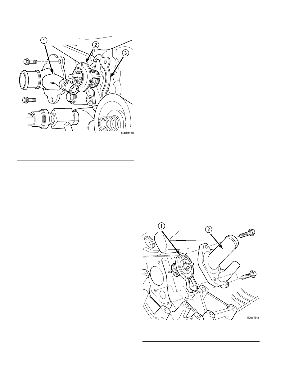
Fig. 8 THERMOSTAT AND HOUSING - 3.5L

1 - THERMOSTAT HOUSING/COOLANT INLET
2 - THERMOSTAT
3 - GASKET

Fig. 9 Thermostat and Housing - 2.7L

1 - THERMOSTAT AND GASKET
2 - THERMOSTAT HOUSING/COOLANT INLET

LH

ENGINE

7 - 23

ENGINE COOLANT THERMOSTAT (Continued)

INSTALLATION

(1) Clean gasket sealing surfaces.

NOTE: Install thermostat with the bleed valve
located at the 12 o’clock position.

(2) Install thermostat and gasket into the thermo-

stat housing.

(3) Install thermostat and housing to cylinder

block. Tighten attaching bolts to 12 N·m (105 in. lbs.)
(Fig. 9).

(4) Connect the heater return and radiator lower

hoses to the thermostat housing. Install hose clamps.

(5) Install the heater hose tube bracket bolt.
(6) Install the transaxle dipstick tube bracket

attaching bolt.

(7) Install the generator support strut.
(8) Connect the generator electrical connector.
(9) Install the left engine mount (Refer to 9 -

ENGINE/ENGINE

MOUNTING/LEFT

MOUNT

-

INSTALLATION).

(10) Lower vehicle.
(11) Inspect and replace dipstick O-ring as neces-

sary. Install the engine oil dipstick and tube.

(12) Refill cooling system (Refer to 7 - COOLING -

STANDARD PROCEDURE).

(13) Connect negative cable to remote jumper ter-

minal.

ENGINE COOLANT
THERMOSTAT - 3.5L

REMOVAL

WARNING: DO NOT REMOVE PRESSURE CAP
WITH THE SYSTEM HOT AND UNDER PRESSURE
BECAUSE SERIOUS BURNS FROM COOLANT CAN
OCCUR.

(1) Disconnect negative cable from remote jumper

terminal.

(2) Drain cooling system (Refer to 7 - COOLING -

STANDARD PROCEDURE).

(3) Raise vehicle on hoist.
(4) Disconnect electrical connectors from engine oil

and power steering pressure switches.

(5) Disconnect radiator and heater hoses from

thermostat housing.

(6) Remove thermostat housing bolts (Fig. 10).
(7) Remove housing, thermostat, and gasket.

NOTE: The OEM thermostat is staked in place at the
factory. To ensure proper seating of replacement
thermostat, carefully remove the bulged metal from
the thermostat housing using a suitable hand held
grinder. It is not necessary to restake the replace-
ment thermostat into the thermostat housing.

INSTALLATION

NOTE: The OEM thermostat is staked in place at the
factory. To ensure proper seating of replacement
thermostat, carefully remove the bulged metal from
the thermostat housing using a suitable hand held
grinder. It is not necessary to restake the replace-
ment thermostat into the thermostat housing.

(1) Clean gasket sealing surfaces.
(2) Install thermostat and gasket into thermostat

housing. For ease of installation, install bolts in
housing for thermostat and gasket retention.

(3) Install thermostat and housing to cylinder

block (Fig. 10). Tighten bolts to 12 N·m (105 in. lbs.).

(4) Connect heater and radiator hoses and install

hose clamps.

(5) Connect electrical connectors to engine oil and

power steering pressure switches.

(6) Lower vehicle and connect negative cable to

remote jumper terminal.

(7) Refill cooling system (Refer to 7 - COOLING -

STANDARD PROCEDURE).

(8) Connect negative cable to remote jumper termi-

nal.

Fig. 10 Thermostat and Housing - 3.5L

1 - THERMOSTAT HOUSING/COOLANT INLET
2 - THERMOSTAT
3 - GASKET

7 - 24

ENGINE

LH

ENGINE COOLANT THERMOSTAT - 2.7L (Continued)

HEATER SUPPLY TUBE - 2.7L

REMOVAL

WARNING: DO NOT REMOVE PRESSURE CAP
WITH THE SYSTEM HOT AND UNDER PRESSURE
BECAUSE SERIOUS BURNS FROM COOLANT CAN
OCCUR.

(1) Drain cooling system. (Refer to 7 - COOLING -

STANDARD PROCEDURE)

(2) Remove radiator upper crossmember. (Refer to

23 - BODY/EXTERIOR/GRILLE OPENING REIN-
FORCEMENT - REMOVAL)

(3) Remove radiator upper hose at tube.
(4) Remove heater hose from heater tube at rear of

engine.

(5) Disconnect heater tube from retaining clip at

rear of engine.

(6) Disconnect electrical connector from coolant

temperature sensor.

(7) Remove screws attaching heater tube to outlet

connector (Fig. 11).

(8) Disengage heater tube from outlet connector

(Fig. 11). To remove heater tube, move forward until
the tube clears cylinder heads.

INSTALLATION

(1) Inspect heater tube O-ring. Replace as neces-

sary.

(2) Lubricate O-ring with a silicone type grease

such as Mopar

t Dielectric Grease.

(3) Install the heater tube by inserting tube in-be-

tween cylinder heads. Insert tube into water outlet
housing (Fig. 11).

(4) Attach heater tube to the retaining clip at rear

of engine.

(5) Install attaching screws and tighten to 3 N·m

(30 in. lbs.).

(6) Install radiator upper and heater hoses to

heater tube.

(7) Connect electrical connector to coolant temper-

ature sensor.

(8) Install radiator upper crossmember. (Refer to

23 - BODY/EXTERIOR/GRILLE OPENING REIN-
FORCEMENT - INSTALLATION)

(9) Fill cooling system. (Refer to 7 - COOLING -

STANDARD PROCEDURE)

HEATER SUPPLY TUBE - 3.5L

REMOVAL

WARNING: DO NOT REMOVE PRESSURE CAP
WITH

SYSTEM

HOT

AND

UNDER

PRESSURE

BECAUSE SERIOUS BURNS FROM COOLANT CAN
OCCUR.

(1) Drain cooling system. (Refer to 7 - COOLING -

STANDARD PROCEDURE)

(2) Remove upper and lower intake manifold.

(Refer to 9 - ENGINE/MANIFOLDS/INTAKE MANI-
FOLD - REMOVAL)

(3) Position lower intake manifold upside down on

bench and remove the tube retaining bolt (Fig. 12).

(4) Remove tube from manifold and discard O-ring.

Fig. 11 Heater Supply Tube - Removal/Installation

1 - OUTLET CONNECTOR
2 - SCREW (2)
3 - HEATER TUBE
4 - O-RING

LH

ENGINE

7 - 25

INSTALLATION

(1) Clean heater tube sealing surfaces.
(2) Inspect heater tube O-ring. Replace as neces-

sary.

(3) Lubricate O-ring with a silicone type grease

such as Mopar

t Dielectric Grease.

(4) Install O-ring on heater tube (Fig. 12).
(5) Install heater tube on manifold.
(6) Install retaining bolts and tighten to 12 N·m

(105 in. lbs.) (Fig. 12).

(7) Install lower and upper intake manifolds.

(Refer to 9 - ENGINE/MANIFOLDS/INTAKE MANI-
FOLD - INSTALLATION)

(8) Refill cooling system. (Refer to 7 - COOLING -

STANDARD PROCEDURE)

HOSE CLAMPS

DESCRIPTION

The cooling system utilizes both worm drive and

spring type hose clamps. If a spring type clamp
replacement is necessary, replace with the original
Mopar

t equipment spring type clamp. To identify

size of spring hose clamps, the size in millimeters
has been stamped on each clamp (Fig. 13). Refer to
HOSE CLAMP USAGE CHART for proper size and
location of hose clamps.

HOSE CLAMP USAGE CHART

SPRING CLAMP LOCATION

2.7L

3.5L

Upper

Radiator Hose

@ engine

39 mm

47 mm

@ radiator

39 mm

39 mm

Lower

Radiator Hose

@ engine

40 mm

39 mm

@ radiator

39 mm

39 mm

Heater Hoses

3/4

9

27 mm

27 mm

3/8

9

17 mm

17 mm

OPERATION

The worm type hose clamp uses a specified torque

value to maintain proper tension on a hose connection.

The spring type hose clamp applies constant ten-

sion on a hose connection. To remove a spring type
hose clamp, use Special Tool 6094 or equivalent, con-
stant tension clamp pliers (Fig. 14) to compress the
hose clamp.

Fig. 13 Spring Clamp Size Location

1 - SPRING CLAMP SIZE LOCATION

Fig. 14 HOSE CLAMP TOOL

1 - HOSE CLAMP TOOL 6094
2 - HOSE CLAMP

Fig. 12 Heater Supply Tube - 3.2/3.5L

1 - COOLANT TEMPERATURE SENSOR
2 - O-RING
3 - BOLT
4 - HEATER SUPPLY TUBE
5 - BOLT

7 - 26

ENGINE

LH

HEATER SUPPLY TUBE - 3.5L (Continued)


Content   ..  50  51  52  53   ..