Chrysler Le Baron, Dodge Dynasty, Plymouth Acclaim. Manual - part 588


  Index      Chrysler     Chrysler Le Baron, Dodge Dynasty, Plymouth Acclaim - service repair manual 1993 year


Search            


Content   ..  586  587  588  589   ..


Chrysler Le Baron, Dodge Dynasty, Plymouth Acclaim. Manual - part 588


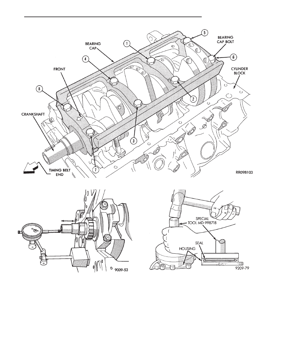
(3) Apply light coating of engine oil to the entire

circumference of oil seal lip.

(4) Install seal assembly on cylinder block and

tighten bolts to 12 N

Im (104 in. lbs.)

FRONT CRANKSHAFT OIL PUMP AND OIL
SEAL

(1) Install oil pump gasket and oil pump case

(Figs. 1 and 14).

CAUTION: Install bolts, depending on length in lo-
cations shown in (Fig. 14).

(2) Using front crankshaft oil seal installer Special

Tool MB998306 install oil seal in oil pump (Fig. 15).

CYLINDER BLOCK

Inspect cylinder block for scratches, cracks and rust

or corrosion, and repair or replace as required.

Fig. 10 Crankshaft Main Bearing Cap

Fig. 11 Checking Crankshaft End Play

Fig. 12 Install Crankshaft Rear Oil Seal

Ä

3.0L ENGINE

9 - 89

(1) Clean cylinder block and check top surface for

distortion with a straight edge and thickness gauge
(Fig. 16).

(2) Top surface must be flat within:

• Standard Value: 0.05 mm (.002 inch)

• Service Limit 0.1 mm (.003 inch)

CAUTION: Maximum of 0.2mm (.008 inch) is permit-
ted. This is a combined total dimension of stock re-
moval from cylinder head (if any) and block top
surface.

BORING CYLINDER

Examine cylinder walls for scuffs, scoring and mea-

sure cylinder bore for out-of-round or taper. If defec-
tive, bore cylinder to oversize. Measure at points
shown in (Fig. 17).

Four oversize pistons are available (0.25mm (.010

inch) 0.50mm (.020 inch) 0.75mm (.030 inch) and
1.0mm (.039 inch). Determine oversize piston on ba-
sis of largest cylinder bore.

(1) Bore to specified clearance between the piston

O.D. and cylinder. The measuring point of the piston
O.D. is shown in (Fig. 18).

(2) Based on measured piston O.D., calculate bor-

ing finish dimension. Boring finish dimension equals
piston O.D. plus 0.03 to 0.05 mm (.0012 to .002 inch)

Fig. 13 Apply Sealant to Oil Seal Housing

Fig. 14 Oil Pump

Fig. 15 Crankshaft Front Oil Seal

Fig. 16 Distortion Check

Fig. 17 Measure Cylinder Bore

9 - 90

3.0L ENGINE

Ä

(clearance between piston O.D. and cylinder) minus
0.02 mm which is the boring margin.

(3) Bore all cylinders to calculated boring finish di-

mension. Then bore the final finish dimension (piston
O.D. plus cylinder clearance).

(4) Check clearance between piston and cylinder,

clearance should be 0.03 to 0.05 mm (.0012 to .002
inch).

ENGINE LUBRICATION SYSTEM

The lubrication system is a full flow filtration pres-

sure feed type. Oil, stored in the oil pan, is taken in
and discharged by a internal gear type oil pump di-
rectly coupled to the crankshaft and its pressure is
regulated by a relief valve. The oil is fed through an
oil filter and to the crankshaft journals from the oil

gallery in the cylinder block. This gallery also feeds
oil under pressure to the cylinder heads. It then
flows from a camshaft bearing cap on each cylinder
head through passages in the rocker shafts to the
rocker arm pivots, auto lash adjusters, and camshaft
journals (Fig. 1).

Fig. 18 Measure Piston

Fig. 1 Engine Oiling

Ä

3.0L ENGINE

9 - 91

OIL PAN

The oil pan is made of sheet metal and is provided

with a baffle-plate to prevent fluctuations in the oil
level while the vehicle is running (Fig. 2).

OIL PAN SEALING AND INSTALLATION

Oil pan to crankcase sealing is provided with Mo-

par Silicone Rubber Adhesive Sealant or equivalent
gasket material. See Form-In-Place Gaskets in Stan-
dard Service Procedures.

(1) Apply sealant as shown in (Fig. 3).
(2) Install pan and tighten screws to 6 N

Im (50 in.

lbs.) in sequence shown in (Fig. 4).

OIL PUMP SERVICE

The oil pump assembly is mounted on the timing

belt end of the cylinder block with the inner pump
rotor indexed and installed on the crankshaft nose.
(Fig. 5).

The oil pump case also retains the crankshaft front

oil seal and provides oil pan front end closure.

REMOVAL

Remove accessory drive system. Refer to Accessory

Drive Service in this group.

Remove 5 bolts that attach oil pump to block (Fig.

6).

INSPECTION OIL PUMP

(1) Check oil pump case for damage and remove

rear cover.

(2) Remove pump rotors and inspect case for exces-

sive wear.

(3) Measure clearance between case and inner ro-

tor (Fig. 8).

(4) Insert the rotor into the oil pump case (Figs. 9

and 10) and measure clearance with a feeler gauge
as indicated.

Fig. 2 Oil Pan

Fig. 3 Oil Pan Sealing

Fig. 4 Oil Pan Screw Tightening Sequence

Fig. 5 Oil Pump-Installed

Fig. 6 Oil Pump Assembly

9 - 92

3.0L ENGINE

Ä


Content   ..  586  587  588  589   ..