Chrysler Le Baron, Dodge Dynasty, Plymouth Acclaim. Manual - part 585


  Index      Chrysler     Chrysler Le Baron, Dodge Dynasty, Plymouth Acclaim - service repair manual 1993 year


Search            


Content   ..  583  584  585  586   ..


Chrysler Le Baron, Dodge Dynasty, Plymouth Acclaim. Manual - part 585


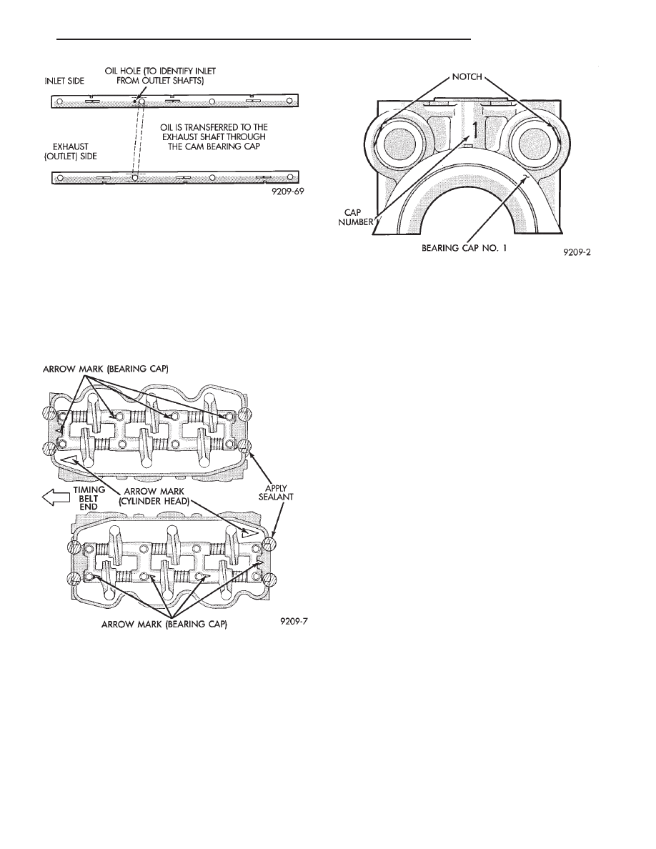
side has a 3mm diameter oil passage hole from the
cylinder head. The exhaust side does not have this
oil passage (Fig. 7).

(1) Check the rocker arm mounting portion of the

shafts for wear or damage. Replace if heavily dam-
aged or worn.

(2) Check oil holes for clogging with small wire,

clean as required (Fig. 7).

REASSEMBLE

(1) Align the camshaft bearing caps with arrows

(depending on cylinder bank) directed as shown in
(Fig. 8) and in numerical order.

Identify number one bearing cap number one and

number four caps are similar (Fig. 9).

(2) Install rocker shafts so that bearing cap num-

ber one with end notches positioned as shown in Fig-
ure 9 that the machined portion of the rocker shaft is
facing down.

(3) Insert attaching bolts to retain assembly.

ASSEMBLE ROCKER ASSEMBLY

Install the rocker arms, bearing caps and springs.

Springs are the same and can be used at all
locations 
on the rocker arm shafts (Figs. 8 and 10).
Insert bolts in number four bearing cap to retain
assembly.

INSTALL ROCKER ARM SHAFT ASSEMBLY

(1) Apply Mopar Silicone Rubber Adhesive Sealant

at bearing cap ends as shown in (Fig. 8).

(2) Install the rocker arm shaft assembly making

sure that the arrow mark on the bearing cap and the
arrow mark on the cylinder head are in the same
direction (Fig. 8).

The direction of arrow marks on the front and

rear assemblies are opposite to each other.

(3) Tighten bearing cap bolts in the following order

to 10 N

Im (85 in. lbs.). First #3, then #2, #1 and #4.

(4) Repeat step 3 increasing the torque to 20 N

Im

(180 in.lbs.).

(5) Install distributor drive adaptor assembly (Fig.

11).

CAMSHAFT OIL SEAL SERVICE— ENGINE
OUT OF VEHICLE

(1) Apply light coat of engine oil to the camshaft oil

seal lip.

(2) Install the oil seal using camshaft oil seal in-

staller tool MD998713 (Fig. 12).

CAMSHAFT END SEAL (PLUG) SERVICE— IN
VEHICLE SERVICE

(1) Remove air cleaner assembly from engine.
(2) Use a small punch and a hammer, carefully

remove cam plug from cylinder head.

(3) Clean the area of the cylinder head where the

new cam plug will be installed.

(4) Apply a light coating of Mopar Silicone Rubber

Adhesive Sealant to the outer diameter of the NEW
cam plug.

(5) Using a suitable installing tool and a hammer,

Fig. 7 Rocker Arm Shaft Identification

Fig. 8 Camshaft Bearing Caps Position

Fig. 9 Number One Camshaft Bearing Cap

Ä

3.0L ENGINE

9 - 77

install the new cam plug to a depth of 0.5mm (0.020
inch) below the surface of the cylinder head.

(6) Replace air cleaner assembly.

CAMSHAFT END SEAL (PLUG) SERVICE —
OUT OF VEHICLE SERVICE

Install end seal plug with Special Tool MD998306.

(Fig. 13).

CYLINDER HEAD

REMOVAL

(1) See Timing System this group for disassembly

and remove camshaft sprockets.

Fig. 10 Assemble Rocker Arm and Shafts

Fig. 11 Distributor Drive

Fig. 12 Install Camshaft Oil Seal

9 - 78

3.0L ENGINE

Ä

(2) See Camshaft Rocker Arms Removal.
(3) Remove upper intake manifold assembly. Refer

to Intake and Exhaust Manifolds, Group 11.

(4) Remove distributor.
(5) Remove exhaust manifolds and cross over Refer

to Intake and Exhaust Manifolds, Group 11.

(6) Remove cylinder head bolts in sequence shown

in (Fig. 14) and remove cylinder head.

INSPECTION

(1) Before cleaning, check for leaks, damage and

cracks.

(2) Clean cylinder head and oil passages.
(3) Check cylinder head for flatness (Fig. 15).
(4) Cylinder head must be flat within;

• Standard dimension = less than 0.05mm (.002
inch)
• Service Limit = 0.2mm (.008 inch)

• Grinding Limit = Maximum of 0.2 mm (.008 inch)
is permitted.

CAUTION: This is a combined total dimension of
stock removal from cylinder head if any and block
top surface.

Fig. 13 Install Camshaft End Seal—Plug

Fig. 14 Cylinder Head Bolt Removal Sequence

Fig. 15 Check Cylinder Head

Fig. 16 Cylinder Head Bolt Tightening Sequence

Ä

3.0L ENGINE

9 - 79

INSTALLATION

(1) Clean surfaces of head and block, install head

gasket over locating dowels.

(2) Install head on locating dowels.
(3) Install 10mm allen hex head bolts with wash-

ers.

(4) Tighten bolts in the order shown in (Fig. 16).

When tightening the cylinder head bolts, tighten
gradually, working in two or three steps and finally
tighten to specified torque of 108 N

Im (80 ft. lbs.).

VALVE SERVICE

VALVE AND VALVE SPRINGS

(1) With suitable valve spring compressor, remove

spring retainer locks, retainer, valve spring, spring
seat and valve (Fig. 17).

(2) Remove valve stem seals with suitable tool

(Fig. 18). Do not reuse valve stem seals.

VALVES

(1) Check valve stem tip for pitting or depression

at point A (Fig. 19).

(2) Check for wear and ridge wear at Point B.
(3) Check for even contact (at face center) with

valve seat, Point C.

(4) Check margin. Replace valve if margin is out of

specification (Fig. 20).

(5) Check valve guide height (Fig. 20).

(6) Measure valve stem to guide clearance. Refer

to specification (Fig. 21).

(7) Measure Valve spring free length and square-

ness (Fig. 22). Refer to (Fig. 21) for specifications.

VALVE SEAT INSPECTION

Inspect the valve seat with Prussian blue to deter-

mine where the valve contacts the seat. To do this,
coat valve seat LIGHTLY with Prussian blue then
set valve in place. Rotate the valve with light pres-
sure. If the blue is transferred to the center of valve
face, contact is satisfactory. If the blue is transferred
to top edge of the valve face, lower valve seat with a
15 degrees stone. If the blue is transferred to the bot-
tom edge of valve face raise valve seat with a 65 de-
gree stone.

(1) Install valve spring seat.

Fig. 17 Remove Valves

Fig. 18 Remove Valve Stem Seals

Fig. 19 Valve Inspection

Fig. 20 Valve Guide Height

9 - 80

3.0L ENGINE

Ä


Content   ..  583  584  585  586   ..