Chrysler Le Baron, Dodge Dynasty, Plymouth Acclaim. Manual - part 583


  Index      Chrysler     Chrysler Le Baron, Dodge Dynasty, Plymouth Acclaim - service repair manual 1993 year


Search            


Content   ..  581  582  583  584   ..


Chrysler Le Baron, Dodge Dynasty, Plymouth Acclaim. Manual - part 583


LEFT SIDE MOUNT

(1) Raise vehicle on hoist and remove left front

wheel.

(2) Remove inter splash shield.
(3) Support the transmission with a transmission

jack.

(4) Remove the insulator thru bolt from the mount.
(5) Remove the transmission mount fasteners and

remove mount.

(6) Reverse removal procedure for installation. En-

sure that the slide tube is seated into the rail
bracket guides. Refer to (Fig. 3) for bolt tightening
specifications.

(7) Engine mount adjustment, Refer to Engine

Mount Insulator Adjustment of this section.

ENGINE MOUNT RUBBER INSULATORS

Insulator location on (right side) and transmission

bracket (left side) are adjustable to allow right/left
drive train adjustment in relation to drive shaft as-
sembly length.

Check and reposition right engine mount insulator

(left engine mount insulator is floating type and will
adjust automatically (Fig. 3). Adjust drive train posi-
tion, if required, for the following conditions:
• Drive shaft distress: See Driveshafts in Suspen-
sion, Group 2.
• Any front end structural damage (after repair).

• Insulator replacement.

ENGINE MOUNT INSULATOR ADJUSTMENT

(1) Remove the load on the engine motor mounts

by carefully supporting the engine and transmission
assembly with a floor jack.

(2) Loosen the right engine mount insulator yoke

screw and two turns on yoke nut, then loosen the
front engine mount bracket to front crossmember
screws and nuts.

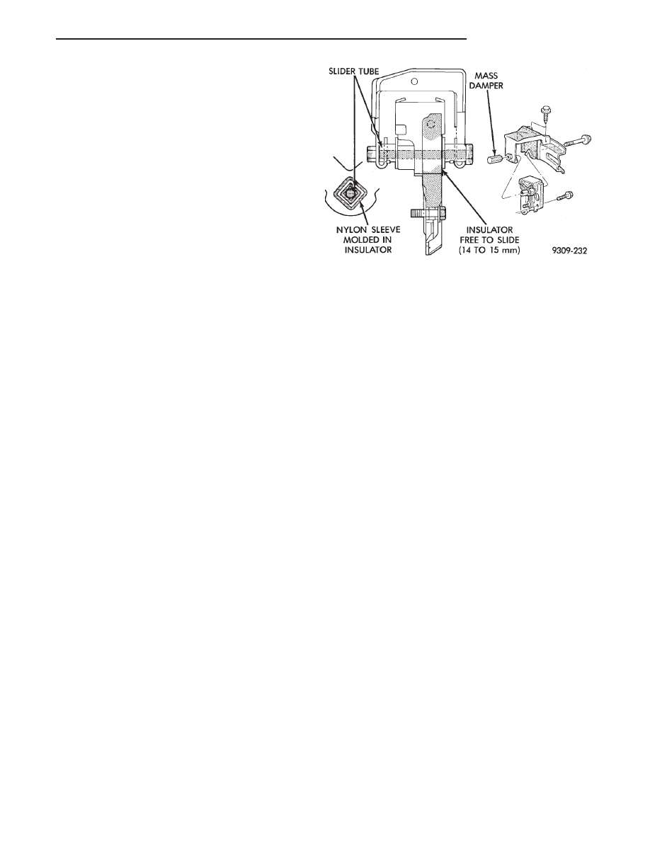
Left engine mount insulator is sleeved over

shaft and long support bolt to provide lateral
movement adjustment with engine weight re-
moved or not.

(3) Pry the engine right or left as required to

achieve the proper drive shaft assembly length. See
Drive Shaft in Suspension Group 2 for driveshaft
identification and related assembly length measur-
ing.

(4) Tighten right engine mount insulator yoke nut

to 102 N

Im (75 ft. lbs.). Then tighten front engine

mount screws and nuts to 54 N

Im (40 ft. lbs.) and

center left engine mount insulator.

(5) Recheck drive shaft length.

ENGINE ASSEMBLY

REMOVAL

(1) Disconnect battery.
(2) Mark hood position at hinges and remove hood.

(3) Drain cooling system. Refer to Cooling System

Group 7 for draining procedure.

(4) Disconnect all electrical connections.
(5) Remove coolant hoses from radiator and en-

gine.

(6) Remove radiator and fan assembly.
(7) See Fuel System Group 14, For procedures to

release fuel pressure, disconnect fuel lines and accel-
erator cable.

(8) Remove air cleaner assembly.
(9) Hoist vehicle and drain engine oil.
(10) Remove air conditioning compressor mounting

bolts and set compressor aside.

(11) Disconnect exhaust pipe at manifold.
(12) Remove transmission inspection cover and

mark flex plate to torque converter position.

(13) Remove screws holding torque converter to

flex plate and attach C-clamp on bottom of converter
housing to prevent torque converter from coming out.

(14) Remove power steering pump mounting bolts

and set pump aside.

(15) Remove

two

lower

transmission

to

block

screws.

(16) Remove starter.
(17) Lower vehicles and disconnect vacuum lines

and ground strap.

(18) Install transmission holding fixture.
(19) Attach engine lifting hoist and support en-

gine.

(20) Remove upper transmission case to block

bolts.

(21) See Engine Mounting in (Fig. 2) and separate

mount/insulators as follows:

(a) Mark RIGHT insulator on right yoke and en-

gine plate supports. Remove insulator to rails
screws.

(b) Remove FRONT engine mount through bolt

and nut.

Fig. 3 Left Insulator Movement

Ä

3.0L ENGINE

9 - 69

(c) Remove LEFT insulator through bolt from in-

side wheelhouse or insulator bracket to transmis-
sion screws.
(22) Remove engine.

INSTALLATION

(1) Attach hoist and lower engine into engine com-

partment.

(2) Align engine mounts and install but do not

tighten until all mounting bolts have been installed.
Tighten bolts to torque specified in (Fig. 2).

(3) Install transmission case to cylinder block,

tighten bolts to 102 N

Im (75 ft. lbs.) torque.

(4) Remove engine hoist and transmission holding

fixture.

(5) Remove C clamp from torque converter hous-

ing. Align flex plate to torque converter and install
mounting screws. Tighten to 75 N

Im (55 ft. lbs.)

(6) Install transmission inspection cover.
(7) Connect exhaust system at manifold.
(8) Install starter.
(9) Install power steering pump and air condition-

ing compressor. For belt installation Refer to Acces-
sory Belt Drive in Cooling System Group 7.

(10) Lower vehicle and connect all vacuum lines.
(11) Connect all electrical connections including

ground strap.

(12) Connect fuel lines and accelerator cable.

(13) Install radiator and fan assembly. Connect fan

motor electrical lead. Install radiator hoses. Fill cool-
ing system. Refer to Cooling System Group 7 for fill-
ing procedure.

(14) Fill engine crankcase with proper oil to cor-

rect level.

(15) Install hood.
(16) Connect battery.
(17) Start engine and run until operating temper-

ature is reached.

(18) Adjust transmission or linkage if necessary.

ACCESSORY DRIVE BELT SERVICE

REMOVAL

(1) Loosen Adjusting Lock Nut (Fig. 6).
(2) Turn adjusting jack screw counterclockwise to

reduce belt tension. Remove belt.

(3) Inspect drive belt for wear and damage (Fig. 5).
(4) Installation: Adjust belt tension to 5/16 deflec-

tion between pulleys (Fig. 6).

(5) Install breaker bar into 1/2 square opening in

tensioner.

(6) Rotate tensioner clockwise to remove and in-

stall belt (Fig. 7).

Fig. 4 Accessories Mounting Brackets

9 - 70

3.0L ENGINE

Ä

ENGINE MOUNT BRACKET

REMOVAL

(1) Remove air conditioning compressor to mount-

ing bracket screws and lay compressor aside (Fig. 4).

(2) Remove screws attaching air conditioning com-

pressor mounting bracket and adjustable drive belt
tensioner from block and engine mounting bracket.
Remove both assemblies.

(3) Remove steering pump/generator belt tensioner

mounting bolt and remove automatic belt tensioner.

(4) Remove two steering pump to engine mounting

bracket screws and one rear support lock nut.

(5) Lay power steering pump aside.
(6) Raise vehicle and remove right inner splash

shield (Fig. 8).

(7) Remove crankshaft drive pulleys and torsional

damper (Fig. 9).

(8) Lower vehicle and place a jack under engine.

Fig. 5 Drive Belt Inspection

Fig. 6 Air Conditioning Belt

Fig. 7 Generator/Power Steering Belt

Fig. 8 Right Inner Splash Shield—Typical

Fig. 9 Crankshaft Drive Pulleys

Ä

3.0L ENGINE

9 - 71

(9) Mark support assembly to engine bracket if as-

sembly is to be used again. Separate engine mount
insulator from engine mount bracket (Fig. 10). Raise
engine slightly.

(10) Remove engine mount bracket (Fig. 10).

(11) Remove timing belt covers (Fig. 11).

TIMING BELT INSPECTION—IN VEHICLE

(1) Remove the upper front outer timing belt cover

by loosening the three attaching bolts. (Fig. 11).

(2) Inspect both sides of the timing belt drive &

back. Replace belt if any of the following conditions
exist.
• Hardening of back rubber back side is glossy with-
out resilience and leaves no indent when pressed
with fingernail.
• Cracks on rubber back.

• Cracks or peeling of canvas.

• Cracks on rib root.

• Cracks on belt sides.

• Missing teeth.

• Abnormal wear of belt sides. The sides are normal
if they are sharp as if cut by a knife (Fig. 12).

(3) If none of the above conditions are seen on the

belt, the belt cover can be reinstalled.

TIMING BELT SERVICE

REMOVAL

(1) Mark belt running direction for installation

(Fig. 14).

(2) Loosen timing belt tensioner bolt (Fig. 16) and

remove timing belt.

(3) Remove crankshaft sprocket flange shield (Fig.

9).

CAMSHAFT SPROCKETS

REMOVAL

(1) Hold camshaft sprocket with Spanner Tool

MB990775 loosen and remove bolt and washer (Fig.
15).

(2) Remove camshaft sprocket from camshaft.

Fig. 10 Right Engine Mount and Engine Mount

Bracket

Fig. 11 Timing Belt Covers

Fig. 12 Timing Belt Inspection

9 - 72

3.0L ENGINE

Ä


Content   ..  581  582  583  584   ..