Chrysler Le Baron, Dodge Dynasty, Plymouth Acclaim. Manual - part 362


  Index      Chrysler     Chrysler Le Baron, Dodge Dynasty, Plymouth Acclaim - service repair manual 1993 year


Search            


Content   ..  360  361  362  363   ..


Chrysler Le Baron, Dodge Dynasty, Plymouth Acclaim. Manual - part 362


GENERAL INFORMATION

CONTENTS

page

page

CIRCUIT IDENTIFICATION

. . . . . . . . . . . . . . . . . 3

COMPONENT IDENTIFICATION

. . . . . . . . . . . . . 3

CONNECTORS

. . . . . . . . . . . . . . . . . . . . . . . . . . . 4

FUSIBLE LINKS

. . . . . . . . . . . . . . . . . . . . . . . . . 4

HARNESS REPAIR

. . . . . . . . . . . . . . . . . . . . . . . 4

LOCATING A SYSTEM

. . . . . . . . . . . . . . . . . . . . 3

SECONDARY IGNITION WIRING

. . . . . . . . . . . . 1

SPLICE LOCATIONS

. . . . . . . . . . . . . . . . . . . . . . 3

SYMBOLS, FUSES AND RELAYS

. . . . . . . . . . . 7

TROUBLESHOOTING WIRING PROBLEMS

. . . . 4

WIRE CODE IDENTIFICATION

. . . . . . . . . . . . . . 2

WIRING DIAGRAM SHEETS AND INDEXES

. . . 1

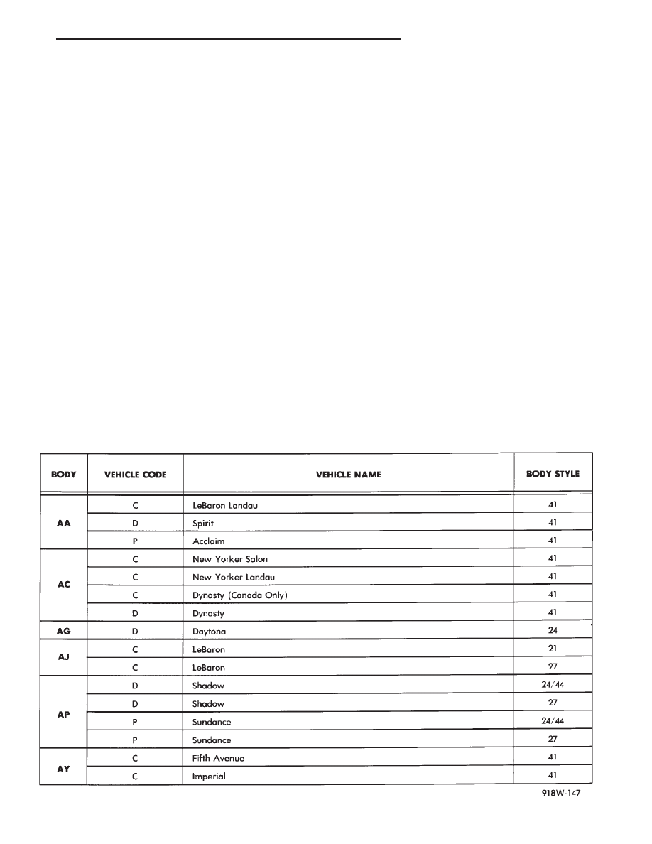
The wiring diagrams contain the latest information

at the time of publication. Throughout this group ref-
erences may be made to a particular vehicle by letter
or number designation. A chart showing the break-
down of these designations is included below.

SECONDARY IGNITION WIRING

Secondary ignition wiring is shown in Figures 1, 2,

3, 4, and 5. For information on distributor operation
or ignition systems refer to Group 8D Ignition Sys-
tems.

WIRING DIAGRAM SHEETS AND INDEXES

The diagrams are organized to show the basic ve-

hicle and all of its options. Add-on or non-factory op-
tions are not covered. The diagram pages are
identified by a sheet number which is located at the
lower right or left hand corner of each sheet. Page
numbers at the top of each page do not apply to
diagram sheets.

Diagram sheets show all information relating to

the system. This includes feeds, grounds, switch in-
ternal circuity, connectors, splices, and pin identifica-
tion for controllers and modules.

1993 MODEL CHART

Ä

GENERAL INFORMATION

8W - 1

In certain instances a wire may be referenced to

another sheet. When this happens, the wire will be
identified as to what it is ie: feed, ground, etc, and
where its going (Fig. 6). This has been done to aid in
the diagnosis of wiring and component problems.

The index used for the diagrams is located at the be-

ginning of the section. And is in alphabetical order to
identify the main system and all related components.

WIRE CODE IDENTIFICATION

Each wire shown in the diagrams contains a code

(Fig. 7) which identifies the main circuit, part of the
main circuit, gauge of wire, and color. The color is
shown as a two letter code which can be identified by
referring to the Wire Color Code Chart (Fig. 8). If
the wire has a tracer and it is a standard color an
asterisk will follow the main wire color. If the tracer

Fig. 2 Secondary Ignition Wiring 2.2L Turbo III

Fig. 3 Distributor Cap 3.0L V6 Engine

Fig. 1 Secondary Ignition Wiring 2.2L and 2.5L

Engine

Fig. 4 Secondary Ignition Wiring 3.0L V6 Engine

Fig. 5 Secondary Ignition Wiring 3.3L and 3.8L V6

Engine

8W - 2

GENERAL INFORMATION

Ä

is non-standard the main wire color will have a slash
(/) after it followed by the tracer color.

CIRCUIT IDENTIFICATION

All circuits in the diagrams use an alpha/numeric

code to identify the wire and its function. To identify
which circuit code applies to a system, refer to the
Circuit Identification Code Chart. This chart shows
the main circuits only and does not show the second-
ary codes that may apply to some models.

LOCATING A SYSTEM

To locate a system or component in the diagrams,

refer to the alphabetical index at the front of the di-
agrams. Determine the diagram sheet number. Sheet
numbers are located at the lower right or left hand
corner of each sheet. Page numbers at the top of
the page do not apply to diagram sheets.

The diagram index identifies the main system and

all components in that system. There are also sec-
tions of the index that identify specific components
only (for example modules, lamps, etc.). Refer to a
components name in the index if you are unclear as
to what a system may be called.

Diagram pages are arranged starting with the bat-

tery and fuses. Then working into charging, starting,
and ignition systems. After this they start at the
front of the vehicle and work to rear of the vehicle.
The diagrams end with connector identification
pages.

COMPONENT IDENTIFICATION

When looking for a components location on the ve-

hicle refer to the wiring and components section.
This section shows the wire harness routing and the
components location in the vehicle. To use this sec-
tion refer to the wiring diagrams for the location of
the component. Then use the component identifica-
tion index to locate the proper figure number.

SPLICE LOCATIONS

Splices are indicated in the diagrams by a diamond

with a splice circuit code within it (Fig. 9 example 1).
If there is more than one splice per circuit a small
box will be connected to it with the splice number in
it (Fig. 9 example 2).

To locate a splice in the wiring harness determine

the splice number from the wiring diagrams then re-
fer to the splice location index. This section shows
the general location of the splice in the harness.

Fig. 6 Wiring Diagram Page Sample

Fig. 7 Wire Color Code Identification

Fig. 8 Wire Color Code Chart

Ä

GENERAL INFORMATION

8W - 3

The wiring diagrams also indicate what harness

the splice is located in. To identify the harness an
abbreviated call out is placed next to the main splice
(Fig. 6).

CONNECTORS

Connectors shown in the diagram sheets are

viewed from the terminal end unless otherwise spec-
ified. For viewing bulkhead, powertrain control mod-
ule, and transmission control module connectors refer
to the rear of the wiring diagrams. This area shows
major connectors for pin and cavity information.

TROUBLESHOOTING WIRING PROBLEMS

When troubleshooting wiring problems there are

six steps which can aid in the procedure. The steps
are listed and explained below.

(1) Verify the problem.
(2) Verify any related symptoms. Perform opera-

tional checks on components that are in the same cir-
cuit as the problem area. Refer to the wiring
diagram fuse application chart.

(3) Analyze the symptoms. Use the wiring dia-

grams to determine what the circuit is doing, where
the problem most likely is occurring and where the
diagnosis will continue.

(4) Isolate the problem area.

(5) Repair the problem.
(6) Verify proper operation. For this step check for

proper operation of all items on the circuit repaired.
Refer to the wiring diagram fuse application chart.

FUSIBLE LINKS

Vehicle wiring harnesses are equipped with fusible

links to protect the harness in the event of a short in
the system. Fusible links are color coded to indicate
wire gauge and size. Refer to the fusible link chart
for color and gauge identification (Fig. 10).

HARNESS REPAIR

FUSIBLE LINK REPLACEMENT

CAUTION: Do not replace blown fusible links with a
standard wire. Only use fusible type wire with hyp-
alon insulation or damage to the electrical system
could occur. Also make sure correct gauge of wir-
ing is used. Refer to the wiring diagrams for proper
gauge and color.

Fig. 9 Wiring Splice Examples

Fig. 10 Fusible Link Chart

8W - 4

GENERAL INFORMATION

Ä


Content   ..  360  361  362  363   ..