Chrysler Le Baron, Dodge Dynasty, Plymouth Acclaim. Manual - part 361


  Index      Chrysler     Chrysler Le Baron, Dodge Dynasty, Plymouth Acclaim - service repair manual 1993 year


Search            


Content   ..  359  360  361  362   ..


Chrysler Le Baron, Dodge Dynasty, Plymouth Acclaim. Manual - part 361


(3) Check for tone in any other function.

CONDITION: NO FASTEN SEAT BELT LAMP
WHEN IGNITION SWITCH IS TURNED ON.

PROCEDURE

(1) Check for burned out lamp.
(2) Check for battery feed at terminal 6 and lamp

output at terminal 3 of chime module.

(3) Check for ignition feed at terminal 4 of chime

module.

CONDITION: FASTEN SEAT BELT LAMP OR
TONE CONTINUE FOR MORE THAN TEN
SECONDS AFTER SEAT BELTS ARE
FASTENED AND DRIVERS DOOR IS CLOSED

PROCEDURE

(1) Check left door jamb switch.
(2) Check chime module.

CONDITION: NO TONE WHEN HEADLAMPS
ARE ON AND DRIVERS DOOR IS OPEN

PROCEDURE

(1) Check left door jamb switch for good ground

when drivers door is open.

(2) Check wiring connector for good contact at

chime module.

(3) Check for battery feed at terminal 6 of chime

module.

(4) Check headlamp switch.

CONDITION: NO TONE WHEN KEY IS LEFT IN
IGNITION AND DRIVERS DOOR IS OPEN

PROCEDURE

(1) Check left door jamb switch for good ground

when drivers door is open.

(2) Check wiring connector for good contact at

chime module.

(3) Check for battery feed at terminal 6 of chime

module.

(4) Check key-in switch.

CONDITION: CHIMES CONTINUE WHEN
HEADLAMPS ARE TURNED OFF AND/OR KEY
IS REMOVED FROM IGNITION

PROCEDURE

(1) Check wiring for a grounded condition between

headlamp switch, key-in switch and chime module.

(2) Check chime module.

CHIME SYSTEM DIAGNOSIS—AC, AG, AJ AND AY
BODIES

CONDITION: NO TONE WHEN IGNITION IS
TURNED ON AND DRIVER’S SEAT BELT IS
UNBUCKLED

PROCEDURE

(1) Check driver’s seat belt buckle switch for a

ground when unbuckled.

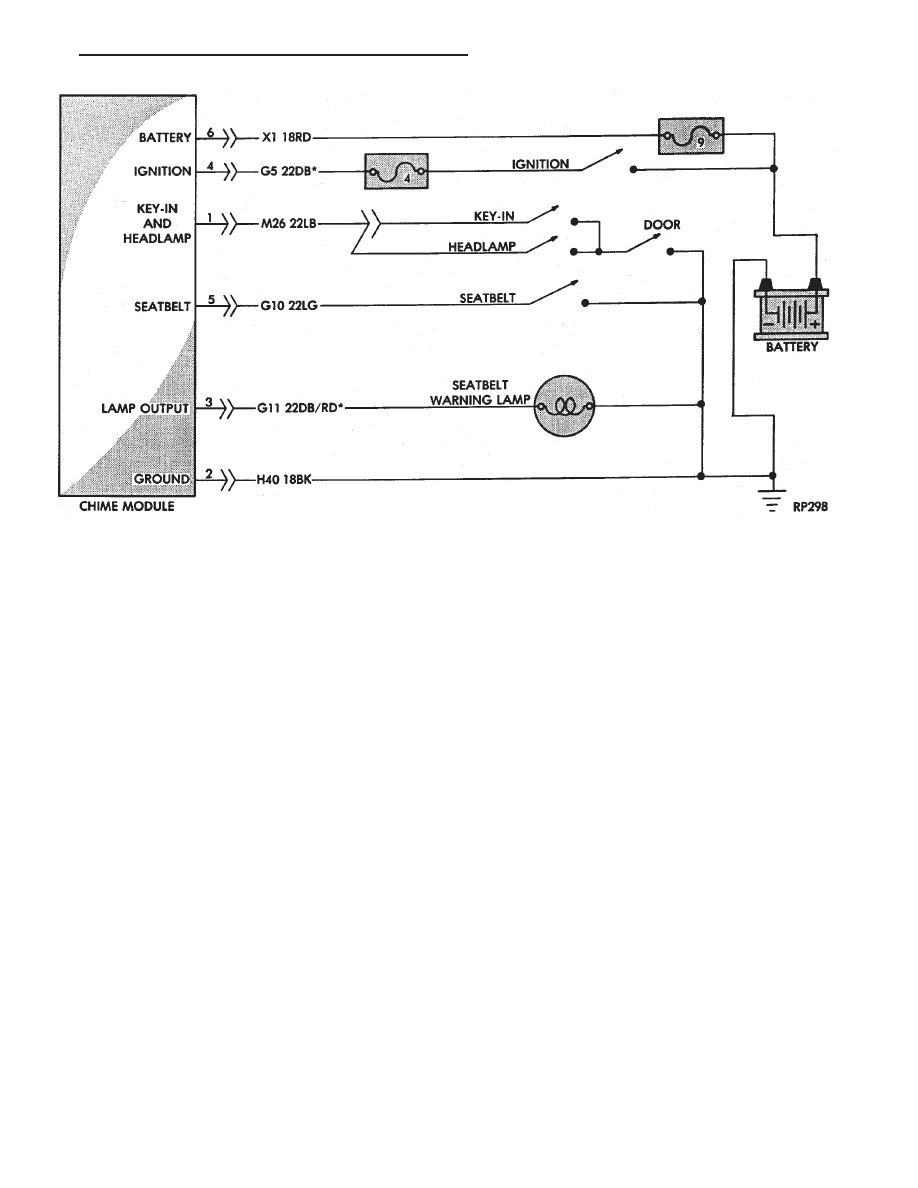
Fig. 5 Chime Module Wiring—AA and AP Bodies

Ä

CHIME WARNING/REMINDER SYSTEM

8U - 3

(2) Check for battery feed at terminal 16 and igni-

tion feed at terminal 12 of 25-way body controller
connector (Fig. 6, 7 and 8).

(3) Check for tone in any other function.

CONDITION: NO FASTEN SEAT BELT LAMP
WHEN IGNITION SWITCH IS TURNED ON

PROCEDURE

(1) Check for burned out lamp.
(2) Check for battery feed at terminal 16 and lamp

output at terminal 21 of 25-way body controller con-
nector.

(3) Check for ignition feed at terminal 12 of

25-way body controller connector.

Fig. 6 Body Controller 25-Way Connector

Fig. 7 Chime System Wiring—AG and AJ Bodies

Fig. 8 Chime System Wiring—AC and AY Bodies

8U - 4

CHIME WARNING/REMINDER SYSTEM

Ä

CONDITION: NO TONE WHEN HEADLAMPS
ARE ON AND DRIVER’S DOOR IS OPEN, AND
IGNITION IS OFF

PROCEDURE

(1) Check left door jamb switch for good ground

when driver’s door is open. This may be checked at
terminal 1 of 25-way body controller connector.

(2) Check for battery feed at terminal 16 of 25-way

body controller connector.

(3) Check headlamp switch.

CONDITION: NO TONE WHEN KEY IS LEFT IN
IGNITION AND DRIVER’S DOOR IS OPEN

PROCEDURE

(1) Check left door jamb switch for good ground

when driver’s door is open. This may be checked at
terminal 1 of 25-way body controller connector.

(2) Check for battery feed at terminal 16 of 25-way

body controller connector.

(3) Check key-in switch.

CONDITION: CHIMES CONTINUE WHEN
HEADLAMPS ARE TURNED OFF AND/OR KEY
IS REMOVED FROM IGNITION

PROCEDURE

Check wiring for a grounded condition between

headlamp switch, key-in switch, and body controller.

SERVICE PROCEDURES

CHIME MODULE REPLACEMENT AA and AP
BODIES

(1) Open glove box door and disconnect check strap.
(2) Disconnect glove box light switch.
(3) Remove screws from glove box assembly and

remove.

(4) Remove two screws from chime module mount-

ing bracket (Figs. 9 and 10).

(5) Disconnect chime module wiring and remove

module.

(6) For installation reverse above procedures.

BODY CONTROLLER REPLACEMENT

Refer to Group 8E, Instrument Panel and Gauges.

SEAT BELT BUCKLE REPLACEMENT

Refer to Group 23, Body of this service manual.

HEADLAMP SWITCH REPLACEMENT

Refer to Group 8E, Instrument Panel and Gauges.

KEY-IN SWITCH REPLACEMENT

The Key-in switch is built into the ignition switch as-

sembly. Should the Key-in switch require service, the
ignition switch assembly must be replaced. Refer to
Group 8D Ignition System of this service manual (Fig.
11).

Fig. 9 Chime Module Location—AA Body

Fig. 10 Chime Module Location

Fig. 11 Halo Lamp and Key-In Warning Switch

Continuity

Ä

CHIME WARNING/REMINDER SYSTEM

8U - 5


Content   ..  359  360  361  362   ..