Chrysler Le Baron, Dodge Dynasty, Plymouth Acclaim. Manual - part 360
AUTOMATIC DAY/NIGHT INSIDE MIRROR
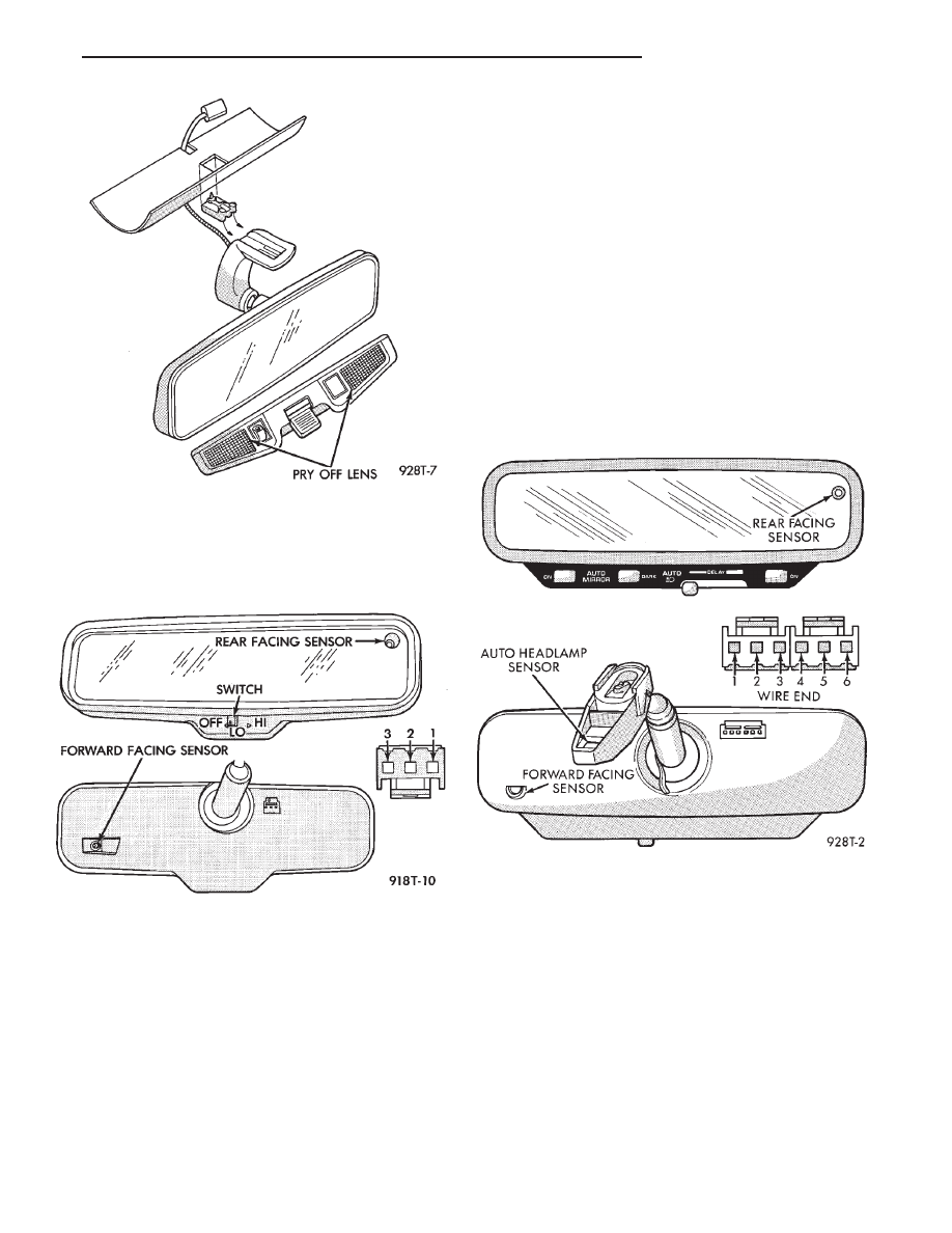
Operational test:
• Turn ignition switch to the ON position with the
vehicle in park (Fig. 21).
• Place mirror switch in the high position.
• Cover the forward facing sensor with dark cloth to
keep out any ambient light.
• Shine a light into the rear facing sensor, watch to
see if the mirror darkens.
With the mirror darkened, place the vehicle in re-
verse, the mirror should return to its normal condi-
tion.
If the above conditions are met the mirror is oper-
ating properly.
• If not test voltage.
Test three way connector harness. Refer to Fig. 21.
(1) Pin 1 Ignition Switch in run position, should
have battery voltage.
(2) Pin 2 Should have continuity to Ground.
(3) Pin 3 When the transmission is in reverse,
should have battery voltage.
(4) If test is OK replace Mirror.
(5) If not refer, to Wiring Diagrams manual to test
the circuits.
AUTOMATIC DAY/NIGHT INSIDE MIRROR WITH
ULTRALIGHT HEADLAMP CONTROL
CAUTION:When JUMP STARTING the vehicle, be-
fore cranking engine turn ignition ON and turn OFF
the Automatic Headlamp Control.
The mirror automatically reduces the amount of
headlamp glare from rear approaching traffic and
provides automatic headlamp control (Fig. 22).
SELF DIAGNOSTIC MODE—OPERATIONAL
TEST:
(1) Place shift selector in park (P) or Neutral (N)
position. With ignition OFF, press and hold AUTO
MIRROR and AUTO LAMP (headlamp) buttons, turn
ignition switch ON. When LED indicators start
flashing, release buttons.
(a) The button LED indicators should flash for
about five seconds.
• AUTO MIRROR
• DARK
• AUTO LAMP
(b) If they continue to flash much longer than
five seconds, the mirror assembly is defective.
Fig. 20 Header Mirror/Reading Lamps
Fig. 21 Automatic Day / Night Mirror
Fig. 22 Automatic Day / Night Mirror with Ultralight
Headlamp Control
Ä
POWER MIRRORS
8T - 7