Chrysler Le Baron, Dodge Dynasty, Plymouth Acclaim. Manual - part 355
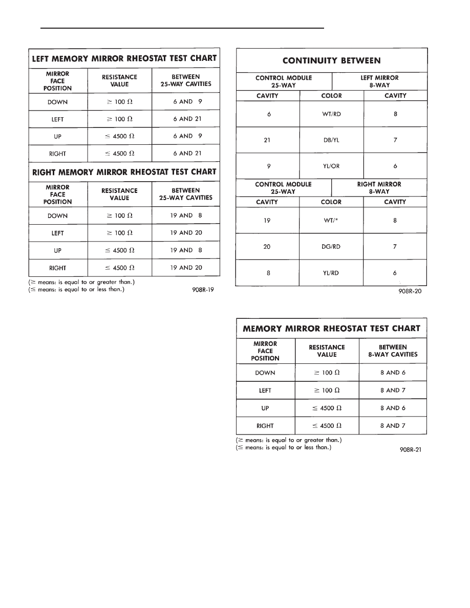
(7) Check for resistance values in the left or right
mirror assembly as indicated by the diagnostic self
test fault locator. Connect an ohmmeter between the
mirror 8-way connector cavities as shown in the
chart (Fig. 29). Both left and right mirrors use the
same cavities. As the mirror face is moved manually
the resistance value will change between the values
given in the chart. If these results are not obtained,
replace the mirror assembly.
(8) If the resistance values from procedure (5) can-
not be obtained and indicate a short to ground or
battery, use an ohmmeter to isolate the circuits and
components at fault. If the fault is in the wiring har-
ness, repair or replace the wiring harness as neces-
sary. If the fault is in the mirror, replace the mirror
assembly.
(9) If after checking the rheostat circuits of an in-
dividual mirror and all circuits are correct then re-
place the control module. Perform the memory seat
diagnostic self check so the control module will learn
the new soft limits of the assembly.
POWER RECLINER MOTOR AND CABLE
REMOVAL
(1) Remove seat assembly from vehicle, following
procedure outlined under Seat Assembly Removal.
(2) Remove seat outboard side shields to expose re-
cliner and cable (Fig. 30).
(3) Remove cable housing clip from cushion frame.
(4) Remove cable housing clamp from the recliner
transmission housing, and remove drive cable.
(5) Lay seat on its back on some clean surface.
(6) Remove four bolts, attaching the power seat
track to cushion frame.
(7) Remove two motor attachment screws from
power seat track cross strap.
(8) Disconnect recliner motor connectors.
Fig. 27 Sensing Rheostat Resistance
Fig. 28 Sensing Rheostat Continuity
Fig. 29 Mirror Rheostat Resistance
Ä
POWER SEATS
8R - 17