Chrysler Le Baron, Dodge Dynasty, Plymouth Acclaim. Manual - part 353


  Index      Chrysler     Chrysler Le Baron, Dodge Dynasty, Plymouth Acclaim - service repair manual 1993 year


Search            


Content   ..  351  352  353  354   ..


Chrysler Le Baron, Dodge Dynasty, Plymouth Acclaim. Manual - part 353


above. When the control module has finished, it will
return to the normal operating mode after ten sec-
onds if no further switches are activated.

The control module will also return to normal op-

erating mode if any manual seat or recliner move-
ment switch is actuated during the ten second
timeout.

If the system has found a problem, refer to the ap-

propriate diagnosis condition.

POWER MEMORY SEAT, RECLINER AND
MIRRORS DIAGNOSIS

Before any diagnosis is done on the system, move

the seat switches and listen for relays clicking in the
control module under the seat. If relays can be heard,
the main battery and ground circuits to the control
module as well as the battery circuit to the switches
in the driver’s door are good.

When checking for voltage or continuity, always

use a volt/ohm meter to get accurate readings. The
seat and recliner switches must be activated to check
for voltage at the seat and recliner motors or at the
input to the control module from the switches.

The control module creates a special voltage supply

for the position sensing functions. It also shuts down
after five seconds, in order to check this or any other
voltage being fed back to the control module. A
switch may have to be activated more than once to
verify a voltage reading. The voltage from the con-
trol module that feeds the seat and recliner position
sensing potentiometer, will be between 4.5 to 5 volts.
For simplicity in the diagnosis section, the feed volt-
age will be called 5 volts. On the position sensing
wires, these voltages will always be less than 5 volts
but more than 0 volts. Typically the high level is at
a maximum of about 4.25 volts and the low level can
be as little as 0.1 volts.

If any seat or recliner potentiometer or mirror

rheostat position sense wires are crossed, the control
module will not move that part of the system. The
seat or mirror will be in a fault diagnostic mode.

CONDITION: SYSTEM WILL NOT OPERATE.

PROCEDURE

(1) Check for forward/rearward operation of re-

cliner. If not operable, check for an open or loose cir-
cuit breaker mounted in board on the relay bank in
cavity 15.

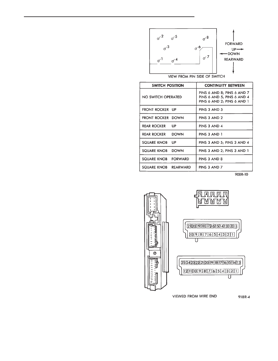
(2) Check for continuity between 2-way connector

under driver’s seat and pin 1 at control module 10-
way connector (Fig. 16 and 17).

(3) Check for continuity between 2-way connector

under driver’s seat and pin 6 at control module 10-
way connector.

(4) Check for any movement of the seat by operat-

ing the seat switch.If movement the circuit is good
into the control module.

(5) No movement check for an open or loose fuse in

cavity 15 of the fuse block.

(6) Check for battery voltage to pin 3 of driver’s

power seat switch.

Fig. 16 Memory Seat Switch Continuity

Fig. 17 Memory Seat Module Connectors

Ä

POWER SEATS

8R - 9

(7) If battery is good, check for continuity of driv-

er’s power seat switch. Refer to Power Memory Seat
Switch Continuity (Fig. 16).

(8) Check that all connectors are securely plugged

into control module under driver’s seat with no ter-
minal push outs.

(9) No correctable faults are found in the above

steps. The battery voltage and ground circuits are
good into the control module. There is battery volt-
age through the seat switch to the control module.
Then replace the control module.

(10) If the control module must be replaced, open it

and observe the non-relay side of the printed circuit
board. The module may be damaged by an intermit-
tent short on the inside of the recliner switch. If a
trace is burnt open near the 10-way connector, may
be caused by the recliner switch (Fig. 18).

(11) If module is burnt, remove recliner switch.

Open the switch and observe the movable contacts
staking at the staked end. If the contact, arm can be
rotated, by a sideways motion, the switch must be re-
placed. This will prevent the new control module
from damaged by the switch.

CONDITION: NO RECLINER MOTION
FORWARD OR REARWARD AND NO RELAYS
CAN BE HEARD CLICKING WHEN THE
RECLINER SWITCH IS ACTIVATED.

PROCEDURE

(1) Check for battery voltage at pin 11 of the con-

trol module 21-way connector.

(2) Check for battery voltage at pin 3 of the re-

cliner switch connector.

(3) Check for ground at pin 1 of the control module

21-way connector.

(4) Check for ground at both pins 1 and 5 of re-

cliner switch connector. If ground is missing at only
one of these pins, repair or replace the seat wiring
harness.

(5) If battery voltage and ground are correct to the

recliner switch connector, check continuity of the re-
cliner switch. Refer to Left Power Memory Recliner
Switch Continuity (Fig. 19).

CONDITION: NO RECLINER MOTION
FORWARD, AND A RELAY CAN BE HEARD
CLICKING WHEN THE RECLINER SWITCH IS
ACTIVATED.

PROCEDURE

(1) Check for battery voltage at pin 2 of the control

module 10-way connector with the recliner switch ac-
tivated.

(2) Check for ground at pin 4 of the control module

10-way connector with the recliner switch activated.

(3) If battery voltage and ground are NOT present

at the above pins of the 10-way connector, replace
the control module. If battery and ground are
present, then continue procedure.

(4) Check for battery voltage and ground at re-

cliner motor connector in seat.

(5) If recliner motor will not operate, refer to Ser-

vice Procedure for Recliner Motor and Cable.

CONDITION: NO RECLINER MOTION
REARWARD, AND RELAYS CAN BE HEARD
CLICKING WHEN THE RECLINER SWITCH IS
ACTIVATED.

PROCEDURE

(1) Check for ground at pin 2 of the control module

10-way connector with the recliner switch activated.

Fig. 18 Memory Module Burnt Area

Fig. 19 Memory Recliner Switch Continuity

8R - 10

POWER SEATS

Ä

(2) Check for battery voltage at pin 4 of the control

module 10-way connector with the recliner switch ac-
tivated.

(3) If battery voltage and ground are NOT present

at the above pins of the 10-way connector, replace
the control module. If battery and ground are
present, then continue procedure.

(4) Check for battery voltage and ground at re-

cliner motor connector in seat.

(5) If recliner motor will not operate, refer to Ser-

vice Procedure for Recliner Motor and Cable.

CONDITION: NO RECLINER MANUAL
MOVEMENT FORWARD OR REARWARD,
RECLINER MOVES IN RECALL MODE ONLY.

PROCEDURE

(1) Check wiring harness in seat between control

module and recliner switch for shorted wires to
ground or crossed wires. If the ground pins 1 and 5
are in the wrong cavities of the recliner switch con-
nector, the control module may be damaged. Deter-
mine the cause and replace the control module after
repairing the wiring if necessary.

(2) The recliner moves forward in the recall mode

only. Press the recliner switch in the forward direc-
tion and check for battery voltage at pin 2 of the re-
cliner switch connector and at pin 5 of the 21-way
control module connector.

(3) The recliner moves rearward in the recall mode

only. Press the recliner switch in the rearward direc-
tion and check for battery voltage at pin 4 of the re-
cliner switch connector and at pin 6 of the 21-way
control module connector.

CONDITION: NO RECLINER MOVEMENT IN
THE RECALL MODE, RECLINER WILL MOVE
MANUALLY WITHOUT STALL DETECTION.

PROCEDURE

(1) Check for 5 volts at pin 9 of the control module

21-way connector (This is the 5 volt feed from the
control module to the recliner position sensing resis-
tor.

(2) Check for ground at pin 7 of the 21-way control

module connector. To test for ground, one lead of the
voltmeter must be connected to the 5 volt supply for
the control module. If the sense voltage and ground
are NOT present, at the above pins of the 21-way
control module connector when the recliner switch is
pressed. Replace the control module since an in ad-
vertent application of battery voltage to the circuit
could damaged the control module. If the circuits are
present then continue this procedure.

(3) Check for 5 volts at pin 2 of the black 5-way

connector plugged into the recliner motor end-bell.

(4) Check for ground at pin 4 of the black 5-way

connector plugged into the recliner motor end-bell.

(5) Unplug the black 5-way connector and observe

the male pins for deformation. If deformed, carefully
straighten to mate properly with the connector. Care-
fully reconnect 5-way connector.

(6) Check for a voltage at pin 3 of the black 5-way

connector plugged into the recliner motor end-bell
with the recliner switch activated. Less than 5 volts
when fully forward and more than 0 volts when fully
reclined that is variable when the recliner is moving.
This is the position sense voltage the control module
must have or it will not move the recliner in recall
since it has no reference for movement. To test for
this voltage, one lead of the voltmeter must be con-
nected to either pin 4 of the black 5-way connector or
pin 7 of the 21-way connector. If the above steps
have been followed and the voltage is 0, check for a
seat wiring harness short to ground of this circuit,
repair as necessary, before continuing with this pro-
cedure.

(7) Check for the position sense voltage at pin 3 of

the control module 21-way connector. If the voltage
appears correct, and varies as indicated in step (6)
above and there is continuity back to the 5-way con-
nector, then replace the control module.

CONDITION: NO SEAT OR RECLINER
MOVEMENT FROM THE MANUAL SWITCHES.
SEAT AND RECLINER WILL MOVE IN THE
RECALL MODE ONLY.

PROCEDURE

(1) Check for a stuck switch contact in the recliner

switch mounted in the driver’s left seat side shield.
Refer to the Memory Recliner Switch Continuity
(Fig. 19).

(2) Check for a stuck switch contact in the driver’s

power seat switch. Refer to Memory Seat Switch
Continuity (Fig. 16).

CONDITION: NO MEMORY RECALL OF SEAT,
RECLINER, OR MIRRORS. SEAT, RECLINER,
AND MIRRORS WILL MOVE BY MANUAL
SWITCH ACTUATION ONLY.

PROCEDURE

(1) Check for a stuck switch contact in the memory

switch. Refer to the Memory Switch Continuity (Fig.
20).

(2) Check for battery voltage pin 1 of the memory

switch (Fig. 20).

Ä

POWER SEATS

8R - 11

CONDITION: NO MEMORY RECALL OF SEAT,
RECLINER, OR MIRRORS TO POSITION 1
ONLY. UNABLE TO ENTER DIAGNOSTIC SELF
TEST MODES. POSITION 2 RECALL WORKS.

PROCEDURE

(1) Check for continuity of actuated memory posi-

tion 1 switch. Refer to the Memory Switch Continu-
ity (Fig. 19). If there is continuity, continue with
procedure. If not replace switch.

(2) Check for a terminal push out at pin 2 of the

memory switch connector.

(3) Check for battery voltage at pin 14 of the con-

trol module 25-way connector with position 1 switch
actuated. If battery voltage is OK. There is no termi-
nal push out, and the connector is properly seated.
But no reaction from the control module, manually
move the seat to a different position than 2. To in-
sure that the Position 1 is not simply a duplicate of
Position 2. If there is still no reaction of the control
module to the actuation of the Position 1 button,
then replace the control module.

CONDITION: NO MEMORY RECALL OF SEAT,
RECLINER, OR MIRRORS TO POSITION 2
ONLY. UNABLE TO ENTER DIAGNOSTIC SELF
TEST MODES. POSITION 1 RECALL WORKS.

PROCEDURE

(1) Check for continuity of actuated memory Posi-

tion 2 button. Refer to the Memory Switch Continu-
ity (Fig. 20). If there is continuity, continue with
procedure. If not replace switch.

(2) Check for a terminal push out at pin 3 of the

memory switch connector.

(3) Check for battery voltage at pin 1 of the control

module 25-way connector with Position 2 button ac-
tuated. If battery voltage OK. There is no terminal
push out, and the connector is properly seated. But
no reaction from the control module, manually move
the seat to a different position than 1. To insure that
the position 2 is not simply a duplicate of position 1.
If there is still no reaction of the control module to
the actuation of the 2 switch, then replace the con-
trol module.

CONDITION: ACTUATION OF THE SET
BUTTON WILL NOT SET ANY NEW POSITIONS
IN MEMORY. UNABLE TO ENTER
DIAGNOSTIC SELF TEST MODES. ONLY
PREVIOUSLY SET MEMORY POSITIONS CAN
BE RECALLED.

PROCEDURE

(1) Check

for

continuity

of

actuated

memory

switch Set button. Refer to the Memory Switch Con-
tinuity (Fig. 20). If there is continuity, continue with
procedure. If not replace switch.

(2) Check for a terminal push out at pin 4 of the

memory switch connector.

(3) Check for battery voltage at pin 2 of the control

module 25-way connector with the Set button actu-
ated. If battery voltage is OK, there is no terminal
push out, and the connector is properly seated then
replace the control module.

CONDITION: NO MEMORY POSITIONS CAN BE
RECALLED AND THE MEMORY SEAT
DIAGNOSTIC SELF SWITCH CHECK IS THE
ONLY PART OF SELF TEST THAT WORKS.
THE SEAT MOVES OK WITH MANUAL
SWITCH.

PROCEDURE

(1) Check for continuity of the seat belt buckle

switch in its unbuckled state. Operate the buckle
switch to ensure the contact opens when the seat belt
is buckled.

(2) Check for continuity between pin 2 of the

2-way seat belt buckle switch connector, harness
side, to ground.

(3) Check for continuity between pin 1 of the

2-way seat belt buckle switch connector, harness
side, to pin 13 of the control module 25-way connec-
tor.

CONDITION: MEMORY RECALLS CAN BE
MADE WHILE THE VEHICLE IS IN MOTION
WITH THE SEAT BELT UNBUCKLED.

PROCEDURE

Check for continuity of the circuit between the left

side instrument panel blue 16-way connector cav-

Fig. 20 Memory Switch Continuity

8R - 12

POWER SEATS

Ä


Content   ..  351  352  353  354   ..