Chrysler Le Baron, Dodge Dynasty, Plymouth Acclaim. Manual - part 349


  Index      Chrysler     Chrysler Le Baron, Dodge Dynasty, Plymouth Acclaim - service repair manual 1993 year


Search            


Content   ..  347  348  349  350   ..


Chrysler Le Baron, Dodge Dynasty, Plymouth Acclaim. Manual - part 349


to the deck lid open position. If the pull down limit
switch is depressed at this time, the motor should
stop.

(c) If these results are not obtained, replace the

pull down motor assembly.

REMOTE KEYLESS ENTRY

OPERATION

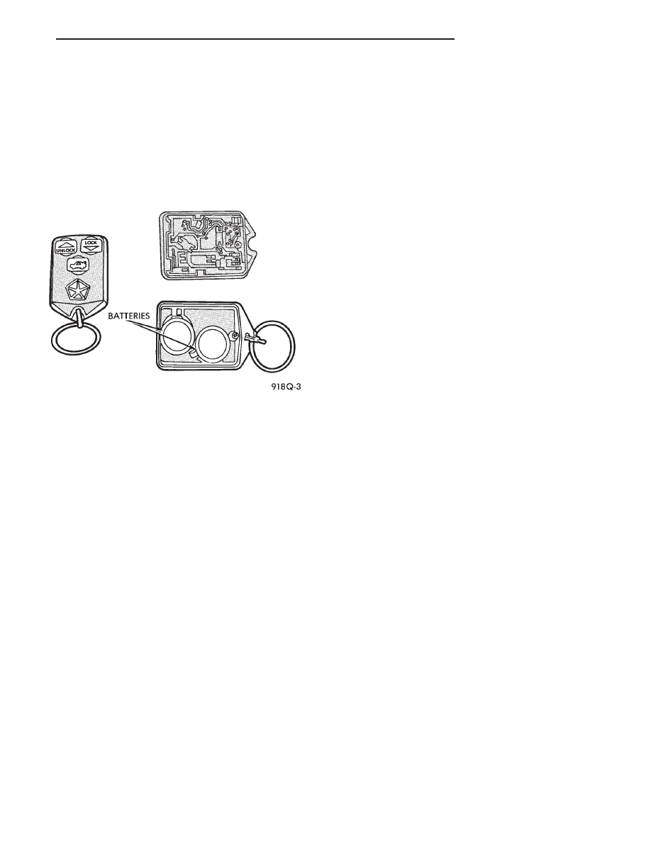
The transmitter has three buttons for operation

(Fig. 11).

• UNLOCK driver’s door, enable illuminated entry,
and disarm the Theft Security System. Pushing and
releasing the button once will unlock the driver’s
door. Two times within five seconds all doors will un-
lock.
• LOCK all doors, set Theft Security System and
chirp horn. Chirp of horn is a short toot to notify
that the alarm system is set and the indicator lamp
on the instrument panel will flash for about 15 sec-
onds.
• Unlock Trunk Lid

• The receiver is capable of retaining VAC even
when power is removed.
• Each receiver must have at least one and no more
than two transmitters.

CONTROL RANGE

Operation range is within 7 meters (23 ft.) of the

receiver.

TRANSMITTER BATTERY

The battery can be removed without special tools

and are readily available at local retail stores. The
recommended battery is Duracell DL 2016 or equiv-
alent. Battery life is about one to two years.

PROGRAM REMOTE KEYLESS ENTRY

(1) Remove trim cover or floor console as needed

that may be covering the Air Bag System Diagnostic
Module (ASDM).

(2) Pull floor carpeting back between the accelera-

tor peddle and ASDM.

(3) Locate program line a dark green wire with a

insulator on the end. Located between the accelerator
and (ASDM).

(4) Turn ignition switch to the ON position.
(5) Connect the program line from the Remote

Keyless Entry Module to ground. The door locks will
lock and unlock to indicate the receiver is ready to
receive transmitter code. Trunk solenoid will not cy-
cle.

(6) Press any button on the transmitter to set code.

If there is a second transmitter it has to be set at
this time. The locks will cycle to confirm program-
ming.

(7) Disconnect the program line from ground. This

returns the system to its normal operation mode.

(8) Replace trim cover or floor console as neces-

sary.

HORN CHIRP CANCELLATION

During the programming operation the horn chirp

can be disabled using the following procedures:

(1) Remove trim cover or floor console as needed

that may be covering the Air Bag System Diagnostic
Module (ASDM).

(2) Pull floor carpeting back between the accelera-

tor peddle and ASDM.

(3) Locate program line a dark green wire with a

insulator on the end. Located between the accelerator
and (ASDM).

(4) Turn ignition switch ON.
(5) Connect the program line from the Remote

Keyless Entry Module to ground. The door locks will
lock and unlock to indicate the receiver is ready to
receive transmitter code. Trunk solenoid will not cy-
cle.

(6) Press any button on the transmitter to set code.

If there is a second transmitter it has to be set at
this time. The locks will cycle to confirm program-
ming.

(7) Press LOCK then UNLOCK transmitter but-

tons repeat three times.

(8) Door locks and rear release will cycle three

times as feedback of Horn Chirp lockout.

(9) Remove ground from program line to restore

normal system operation.

(10) To reinstate the Horn Chirp feature refer to

Program Remote Keyless Entry.

TESTING

CONDITION: When trying to program the receiver

module in the vehicle with a new transmitter and
there is no response from the module, Example: the
door locks do not cycle through a lock/unlock routine.
Refer to Fig. 12 for a block wiring diagram or to
Group 8W, Wiring Diagrams.

Fig. 11 Transmitter

Ä

POWER LOCKS

8P - 5

(1) Be sure that the module has a battery feed

from the 20 Amp breaker in cavity 1 of the black
connector. Also affected would be the optical horn
and the stop lamps.

(2) Be sure that the module has an ignition feed

from 5 Amp fuse in cavity 8 of the black connector.
Also affected would be the body computer, instru-
ment cluster and message center.

(3) Be sure that the module has a ground from the

right side cowl behind the body computer to the cav-
ity 5 of the black connector.

(4) Be sure that you are supplying a good ground

to the programming wire.

(5) If the above circuits are good, replace the Re-

ceiver Module.

CONDITION: Doors can be locked or unlocked with

the Keyless Entry transmitter. But the doors will not
lock. The Vehicle Theft Alarm system will not arm,
when using only the power door LOCK switch in the
driver’s door.

(1) Be sure you have not left key in the ignition

column lock cylinder.

(2) If step 1 is OK, check the Key in Lock switch

circuit in the steering column for a short to ground.

(3) In this problem the body computer controls the

LOCK function. Be sure that it is providing a battery
voltage output to the door lock relay. The door lock
relay controls the door lock motors.

CONDITION: Doors will lock but Vehicle Theft

System will not arm when using the transmitter.

(1) The Keyless Entry Receiver Module controls

the door lock signal to the door lock relay. The door
lock relay controls the door lock motors. Check for
battery voltage at cavity 10 of the Theft Alarm mod-
ule from the Receiver module.

(2) If voltage is OK, replace Receiver module.
CONDITION: All doors except driver’s door will

lock with the transmitter.

(1) Test the driver’s door output of the Receiver

Module for a ground.

(2) If there is no ground at the pin, replace the Re-

ceiver module.

(3) If there is a ground at the output, replace the

door lock motor.

CONDITION: Only driver’s door will lock with the

transmitter.
• Repair ground circuit to unlock relay

• Replace unlock relay

CONDITION: Doors do not lock with the transmit-

ter, but still get horn CHIRP that indicates that they
did lock. Replace Receiver module.

CONDITION: Doors will lock with the transmitter

but there is no horn CHIRP.

(1) Press horn button, listen horn sound.
(2) If the horn sounded, change horn relay.

(3) Still no CHIRP, check continuity between the

horn relay and the receiver output pin. Repair as
necessary.

(4) Still no horn CHIRP, replace the receiver mod-

ule.

(5) If using a DRB II, refer to Body Diagnostic Pro-

cedures.

REMOTE KEYLESS MODULE REPLACEMENT

(1) Remove lower right instrument panel silencer.
(2) Remove glove box assembly.
(3) Remove three screws attaching the mounting

bracket to instrument panel.

(4) Lower bracket and module assembly, to discon-

nect wire connector.

(5) Remove two screws attaching the Remote Key-

less entry Module to bracket.

(6) Remove two screws attaching the security mod-

ule to bracket.

(7) To installation reverse above procedures.

LAMP OUTAGE MODULE REPLACEMENT

(1) Remove lower right instrument panel silencer.
(2) Remove glove box and ash receiver module.
(3) Remove three screws attaching the mounting

bracket to instrument panel.

(4) Lower bracket and module assembly, to discon-

nect wire connectors.

(5) Remove two screws attaching the Lamp Outage

Module to bracket.

(6) Remove two screws attaching the security mod-

ule to bracket.

(7) To installation reverse above procedures.

DOOR LOCK INHIBIT

The power door lock inhibit system prevents the

doors from being locked using the power door locks
when either of two conditions occur:

(1) The key is in the ignition switch and any of the

doors are open. The ignition switch does not have to
be ON.

(2) The key is in the ignition switch and the head-

lamp are on.

AC, AG, AJ AND AY BODIES

With the ignition switch in the ON or OFF position

and the driver’s door open the Body Controller will
ignore the command to lock the power door locks.
Once the key is removed, or the driver’s door is
closed, the Body Controller will allow the power door
locks to lock. Refer to Body Diagnostic Procedure
Manual for further testing procedures.

8P - 6

POWER LOCKS

Ä

Fig. 12 Block Wiring Diagram

Ä

POWER LOCKS

8P - 7

AA BODY

Uses a power door lock inhibit relay. The relay is

located above the glove box compartment.

INHIBIT RELAY

(1) Using a voltmeter, test for battery voltage at

pin 4. If no voltage check fuse 15 (Fig. 13).

(2) Using a ohmmeter, check for continuity to

ground at pin 8. If no continuity to ground, check in-
strument panel ground.

(3) To check pin 5:

(a) The key is in the ignition switch and a door

is open.

(b) The key is in the ignition switch and the

headlamps are ON.

(c) Test for continuity to ground.
(d) If not, the relay contact is open or the relay is

being energized when it should not be. Pin 5 feeds
the ground from the relay to door lock switch.
(4) To check pin 6:

(a) The key is in the ignition switch and a door

is open.

(b) The key is in the ignition switch and the

headlamps are ON.

(c) Test for continuity to ground.
(d) If not, check key in switch, headlamps on

switch and/or door jamb switches. Pin 6, feeds
ground from key in switch to the relay.

Fig. 13 Inhibit Relay Connector

8P - 8

POWER LOCKS

Ä


Content   ..  347  348  349  350   ..