Chrysler Le Baron, Dodge Dynasty, Plymouth Acclaim. Manual - part 345


  Index      Chrysler     Chrysler Le Baron, Dodge Dynasty, Plymouth Acclaim - service repair manual 1993 year


Search            


Content   ..  343  344  345  346   ..


Chrysler Le Baron, Dodge Dynasty, Plymouth Acclaim. Manual - part 345


RESTRAINT SYSTEMS

CONTENTS

page

page

AIR BAG MODULE

. . . . . . . . . . . . . . . . . . . . . . . 4

AIR BAG SERVICE AND TEST PROCEDURES

1

AIR BAG SYSTEM CHECK

. . . . . . . . . . . . . . . . . 3

AIR BAG SYSTEM DIAGNOSTIC MODULE

(ASDM)

. . . . . . . . . . . . . . . . . . . . . . . . . . . . . . 5

CLOCKSPRING

. . . . . . . . . . . . . . . . . . . . . . . . . . 6

CLOCKSPRING CENTERING PROCEDURE

. . . . 6

GENERAL INFORMATION . . . . . . . . . . . . . . . . . . 1
LEFT FRONT IMPACT SENSOR . . . . . . . . . . . . . 4
RIGHT FRONT IMPACT SENSOR

. . . . . . . . . . . 5

SCHEDULED MAINTENANCE INSPECTION

. . . . 3

STEERING COLUMN SWITCHES

. . . . . . . . . . . . 7

STEERING WHEEL

. . . . . . . . . . . . . . . . . . . . . . . 7

AIR BAG SERVICE AND TEST PROCEDURES

WARNING: THIS SYSTEM IS A SENSITIVE, COM-
PLEX ELECTRO-MECHANICAL UNIT. BEFORE AT-
TEMPTING TO DIAGNOSE, REMOVE OR INSTALL
THE AIR BAG SYSTEM COMPONENTS, YOU MUST
FIRST DISCONNECT AND ISOLATE THE NEGATIVE
(GROUND) BATTERY CABLE. FAILURE TO DO SO
COULD RESULT IN ACCIDENTAL DEPLOYMENT
AND POSSIBLE PERSONAL INJURY.

WHEN AN UNDEPLOYED AIR BAG ASSEMBLY

IS TO BE REMOVED FROM THE STEERING
WHEEL, DISCONNECT BATTERY GROUND CA-
BLE AND ISOLATE. ALLOW SYSTEM CAPACI-
TOR TO DISCHARGE FOR TWO MINUTES THEN
BEGIN AIR BAG SYSTEM COMPONENT RE-
MOVAL.

Vehicles equipped with a Air Bag System must be

inspected every three years or 30,000 miles / 48,000
Km. To inspect system use Passive Restraint System
Diagnostic Procedures Manual.

If the Air Bag Module Assembly is defective and

non-deployed, refer to Chrysler Motors current re-
turn list for proper handling procedures.

WARNING: REPLACE AIR BAG SYSTEM COMPO-
NENTS WITH CHRYSLER MOPAR

T

SPECIFIED RE-

PLACEMENT PARTS. SUBSTITUTE PARTS MAY
VISUALLY APPEAR INTERCHANGEABLE, BUT IN-
TERNAL DIFFERENCES MAY RESULT IN INFERIOR
OCCUPANT PROTECTION.

THE FASTENERS, SCREWS, AND BOLTS, ORIG-

INALLY USED FOR THE AIR BAG COMPO-
NENTS, HAVE SPECIAL COATINGS AND ARE
SPECIFICALLY DESIGNED FOR THE AIR BAG
SYSTEM. THEY MUST NEVER BE REPLACED
WITH ANY SUBSTITUTES. ANYTIME A NEW
FASTENER IS NEEDED, REPLACE WITH THE

CORRECT FASTENERS PROVIDED IN THE SER-
VICE PACKAGE OR FASTENERS LISTED IN THE
PARTS BOOKS.

GENERAL INFORMATION

AIR BAG MODULE

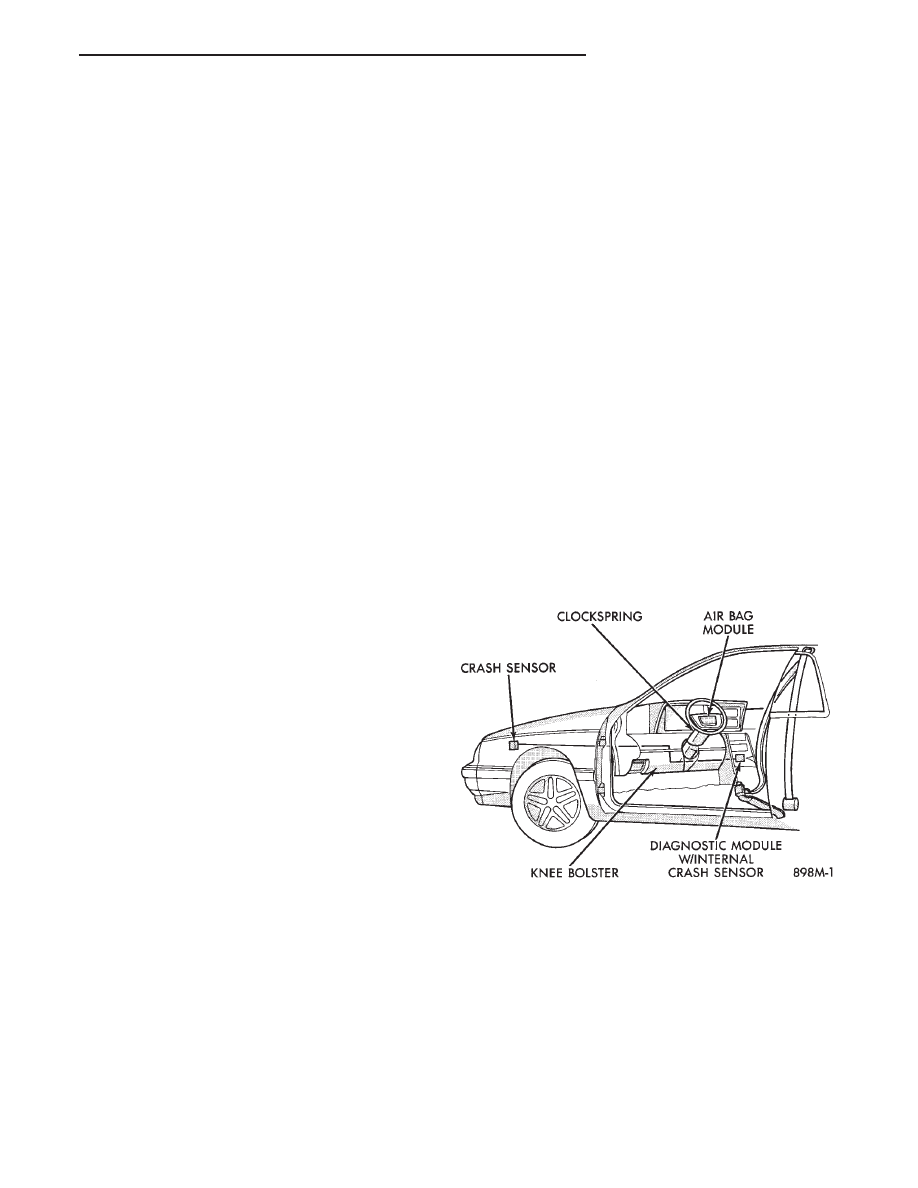
The air bag module is the most visible part of the

system (Fig 1). It contains the air bag cushion and
its supporting components. The air bag module con-
tains a housing to which the cushion and inflator are
attached and sealed.

The inflator assembly is mounted to the back of the

module housing. When supplied with the proper elec-
trical signal the inflator assembly will produce a gas
and discharges it directly into the cushion. A protec-
tive cover is fitted to the front of the air bag module
and forms a decorative cover in the center of the
steering wheel. The air bag module is mounted di-
rectly to the steering wheel.

Fig. 1 Air Bag Passive Restraint System

Ä

RESTRAINT SYSTEMS

8M - 1

FRONT IMPACT SENSORS

The driver air bag system is a safety device de-

signed to reduce the risk of fatality or serious injury,
caused by a frontal impact of the vehicle.

The impact sensors provide verification of the di-

rection and severity of the impact. Three impact sen-
sors are used. One is called a safing sensor. It is
located

inside

the

diagnostic

module

which

is

mounted on the floor pan, just forward of the center
console. The other two sensors are mounted on the
upper crossmember of the radiator closure panel on
the left and right side of the vehicle under the hood.

The impact sensors are threshold sensitive switches

that complete an electrical circuit when an impact
provides a sufficient G force to close the switch. The
sensors are calibrated for the specific vehicle and re-
act to the severity and direction of the impact.

CLOCKSPRING

The clockspring is mounted on the steering column

behind the steering wheel, and is used to maintain a
continuous electrical circuit between the wiring har-
ness and the driver’s air bag module. This assembly
consists of a flat ribbon-like electrically conductive
tape which winds and unwinds with the steering
wheel rotation.

DIAGNOSTIC MODULE

The Air Bag System Diagnostic Module (ASDM)

contains the safing sensor and energy reserve capac-
itor. The ASDM monitors the system to determine
the system readiness. The ASDM will store sufficient
energy to deploy the air bag for only two minutes af-
ter the battery is disconnected. If both front impact
sensors are open the air bag could be deployed up to
9.5 minutes after the battery is disconnected. The
ASDM contains on-board diagnostics, and will illumi-
nate the AIR BAG warning lamp in the cluster when
a fault occurs.

STORAGE

The air bag module must be stored in its original

special container until used for service. Additionally,
it must be stored in a clean, dry environment, away
from sources of extreme heat, sparks, and sources of
high electrical energy. Always place or store the
module on a surface with the trim cover facing up to
minimize movement in case of accidental deploy-
ment.

HANDLING LIVE MODULE

At no time should any source of electricity be per-

mitted near the inflator on the back of the module.
When carrying a live module, the trim cover should
be pointed away from the body to minimize injury in
the event of accidental deployment. In addition, if
the module is placed on a bench or other surface, the

plastic trim cover should be face up to minimize
movement in case of accidental deployment.

When handling a steering column with an air bag

module attached, never place the column on the floor
or other surface with the steering wheel or module
face down.

DEPLOYED MODULE

The vehicle interior may contain a very small

amount of sodium hydroxide powder, a byproduct of
air bag deployment. Since this powder can irritate
the skin, eyes, nose or throat, be sure to wear safety
glasses, rubber gloves and long sleeves during
cleanup (Fig. 2).

If you find that the cleanup is irritating your skin,

run cool water over the affected area. Also, if you ex-
perience nasal or throat irritation, exit the vehicle
for fresh air until the irritation ceases. If irritation
continues, see a physician.

CLEANUP PROCEDURE

Begin the cleanup by putting tape over the two air

bag exhaust vents (Fig. 3) so that no additional pow-
der will find its way into the vehicle interior. Then
remove the air bag and air bag module from the ve-
hicle.

Use a vacuum cleaner to remove any residual pow-

der from the vehicle interior. Work from the outside
in so that you avoid kneeling or sitting in a un-
cleaned area.

Be sure to vacuum the heater and A/C outlets as

well (Fig. 4). In fact it’s a good idea to run the blower
on low and to vacuum up any powder expelled from
the plenum. You may need to vacuum the interior of
the car a second time to recover all of the powder.

Place the deployed bag and module in your auto-

motive scrap.

Fig. 2 Wear Safety Glasses and Rubber Gloves

8M - 2

RESTRAINT SYSTEMS

Ä

SERVICE OF DEPLOYED AIR BAG MODULE

After an air bag has been deployed, the air bag

module and clockspring must be replaced because
they cannot be reused. Other air bag system compo-
nents are replaced if damaged.

SCHEDULED MAINTENANCE INSPECTION

Vehicles equipped with a Air Bag System must be

inspected every three years or 30,000 miles / 48,000
Km. The following items should be inspected.

(1) Inspect components for damage or deteriora-

tion.

(a) If the air bag module housing shows signs of

physical damage or abuse, replace the module.

(b) Check that both front impact sensors are

properly installed to the upper crossmember of the
radiator closure panel. Repair as required.
(2) Check the air bag warning lamp for proper op-

eration as follows:

(a) Turn ignition switch to the ON position, the

air bag warning lamp should light. If not, test the

system using the DRB II and Passive Restraint
System Diagnostic Procedures Manual. Repair as
required.

(b) The air bag warning lamp lights, but fails to go

out after ten seconds. Test the system using the DRB
II and Passive Restraint System Diagnostic Proce-
dures Manual. Repair as required.

(c) Erasing of fault codes is not required.

AIR BAG SYSTEM CHECK

WARNING: BEFORE BEGINNING ANY AIR BAG SYS-
TEM CHECK PROCEDURES, REMOVE AND ISOLATE
THE BATTERY NEGATIVE (-) CABLE (GROUND)
FROM THE VEHICLE BATTERY. THIS IS THE ONLY
SURE WAY TO DISABLE THE AIR BAG SYSTEM.
FAILURE TO DO THIS COULD RESULT IN ACCIDEN-
TAL AIR BAG DEPLOYMENT AND POSSIBLE PER-
SONAL INJURY.

WHEN AN UNDEPLOYED AIR BAG ASSEMBLY IS

TO BE REMOVED FROM THE STEERING WHEEL,
DISCONNECT BATTERY GROUND CABLE AND
ISOLATE. ALLOW SYSTEM CAPACITOR TO DIS-
CHARGE FOR TWO MINUTES, THEN BEGIN AIR
BAG REMOVAL.

(1) Disconnect the battery negative cable and iso-

late.

(2) Remove forward console or cover as necessary.
(3) Connect DRB II to ASDM diagnostic 6-way con-

nector, located at right side of module.

(4) Turn the ignition key to ON position. Exit vehicle

with DRB II. Use the latest version of the proper
cartridge.

(5) After checking that no one is inside the vehicle,

connect the negative battery cable.

(6) Using the DRB II, read and record active fault

data.

(7) Read and record any stored faults.
(8) Refer to the Passive Restraint Diagnostic Test

Manual if any faults are found in steps 6 and 7.

(9) Erase stored faults if there are no active fault

codes. If problems remain, fault codes will not erase.

(10) With the ignition key in the ON position, make

sure no one is in the vehicle.

(11) From the passenger side of vehicle, turn the

ignition key to OFF then ON and observe the instru-
ment cluster air bag lamp. It should go on for 6 to 8
seconds, then go out; indicating system is functioning
normally.

If air bag warning lamp either fails to light,

blinks on and off or goes on and stays on, there is
a system malfunction. Refer to the Passive Re-
straint Diagnostic Test Manual to diagnose the
problem.

Fig. 3 Seal the Air Bag Exhaust Vents

Fig. 4 Vacuum Heater and A/C Outlets

Ä

RESTRAINT SYSTEMS

8M - 3

AIR BAG MODULE

WARNING: BEFORE BEGINNING ANY AIR BAG
SYSTEM REMOVAL OR INSTALLATION PROCE-
DURES, REMOVE AND ISOLATE THE BATTERY
NEGATIVE (-) CABLE (GROUND) FROM THE VEHI-
CLE BATTERY. THIS IS THE ONLY SURE WAY TO
DISABLE THE AIR BAG SYSTEM. FAILURE TO DO
THIS COULD RESULT IN ACCIDENTAL AIR BAG
DEPLOYMENT AND POSSIBLE PERSONAL INJURY.

UNDEPLOYED AIR BAG REMOVAL FROM THE

STEERING

WHEEL:

DISCONNECT

BATTERY

GROUND CABLE AND ISOLATE. ALLOW SYS-
TEM CAPACITOR TO DISCHARGE FOR TWO
MINUTES. BEGIN AIR BAG REMOVAL.

REMOVAL

When removing a deployed module, wear rubber

gloves, eye protection and a long sleeve shirt as de-
posits may be on the surface which could irritate the
skin and eyes.

(1) Disconnect battery negative cable and isolate.
(2) Wait two minutes for the reserve capacitor to

discharge before removing undeployed module.

(3) Remove four nuts attaching air bag module to

steering wheel (Fig. 5).

(4) Lift module, and disconnect electrical connector

from rear of module.

(5) Remove module.
(6) When replacing a deployed module, the clock-

spring must also be replaced. Refer to Clockspring
Removal and Installation for proper procedure.

INSTALLATION

(1) Connect clockspring wiring connector to the

module, by pressing straight in on the connector.

(2) Install four nuts and tighten to 9 to 11 N

Im (80

to 100 in. lbs.) torque.

(3) Do not connect battery negative cable. Refer to

Air Bag System Check for proper procedure.

LEFT FRONT IMPACT SENSOR

REMOVAL

WARNING: BEFORE BEGINNING ANY AIR BAG
SYSTEM REMOVAL OR INSTALLATION PROCE-
DURES, REMOVE AND ISOLATE THE BATTERY
NEGATIVE (-) CABLE (GROUND) FROM THE VEHI-
CLE BATTERY. THIS IS THE ONLY SURE WAY TO
DISABLE THE AIR BAG SYSTEM. FAILURE TO DO
THIS COULD RESULT IN ACCIDENTAL AIR BAG
DEPLOYMENT AND POSSIBLE PERSONAL INJURY.

(1) Disconnect battery negative cable and isolate.
(2) Disconnect speed control servo from battery

tray, if equipped.

(3) Remove battery, battery tray, powertrain con-

trol module and coolant bottle.

(4) Disconnect impact sensor electrical connector.
(5) Remove three screws holding sensor to radiator

closure panel. Remove left sensor (Fig. 6).

INSTALLATION

(1) Mount left sensor (arrow pointed forward) to

engine side of closure panel using three screws pro-
vided with new sensor. Tighten to 10 to 13 N

Im (90

to 120 in. lbs.) torque.

Fig. 5 Air Bag Module

Fig. 6 Left Impact Sensor

8M - 4

RESTRAINT SYSTEMS

Ä


Content   ..  343  344  345  346   ..