Chrysler Le Baron, Dodge Dynasty, Plymouth Acclaim. Manual - part 321
INSTALLATION
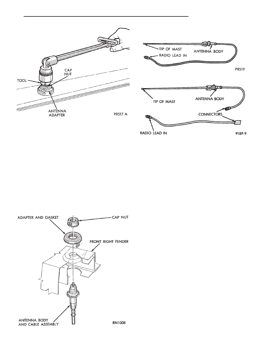
(1) Install antenna body and cable from under-
neath fender (Fig. 12).
(2) Install gasket, adapter, and cap nut. Tighten
cap nut to 14 N
Im (125 in. lbs.) with Antenna Nut
Wrench C-4816.
(3) Install antenna mast into antenna body until
sleeve bottoms on antenna body (Fig. 11).
(4) Route cable to radio if necessary.
BENCH TEST FOR ANTENNA MALFUNCTION
It is also possible to check short or open circuits
with an ohmmeter or continuity light once the an-
tenna has been removed from the vehicle.
(1) Continuity should be present between the tip of
the mast and radio end pin (Fig. 13 and 14).
(2) No continuity should be observed or a very high
resistance of several megohms between the ground
shell of the connector and radio end pin.
(3) Continuity should be observed between the ground
shell of the connector and the mounting hardware.
Wiggle cable over its entire length to reveal inter-
mittent short or open circuits during step 1, 2 and 3.
POWER ANTENNA
OPERATION
The power operated radio antenna (Fig. 15) is a
telescoping type antenna, extended and retracted by a
reversible electric motor.
The Automatic Power Antenna is controlled by a
combination of an external relay and limit switches
built into the antenna motor housing. The antenna is
actuated when radio is switched ON and the ignition
switch in ON or ACCESSORY position. The antenna
mast should extend. When the ignition switch or radio
is turned OFF the antenna mast should fully retract
and declutch.
Many antenna problems may be avoided by frequent
cleaning of the antenna mast telescoping sections. Clean
the antenna mast sections with a clean soft cloth.
Before an antenna is removed, the antenna perfor-
mance should be tested to decide if it is a reception
problem or an operational problem.
Whenever an operational malfunction occurs, first
verify that the radio antenna wire harness is properly
connected. Check all connectors before starting normal
diagnosis and repair procedures. Refer to Power An-
tenna Electrical Diagnosis Chart (Fig. 16).
Fig. 12 Antenna Mounting
Fig. 11 Removing or Tightening Antenna Cap Nut
Fig. 13 Antenna Bench Test Points
Fig. 14 Antenna Bench Test Points—Two Part
Ä
AUDIO SYSTEM
8F - 21