Chrysler Le Baron, Dodge Dynasty, Plymouth Acclaim. Manual - part 320


  Index      Chrysler     Chrysler Le Baron, Dodge Dynasty, Plymouth Acclaim - service repair manual 1993 year


Search            


Content   ..  318  319  320  321   ..


Chrysler Le Baron, Dodge Dynasty, Plymouth Acclaim. Manual - part 320


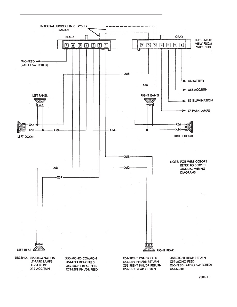
Fig. 2 Radio Connector Circuits

Ä

AUDIO SYSTEM

8F - 17

RADIO REMOVAL—AA BODY

(1) Remove center bezel by pulling straight back

disengaging the five clips.

(2) Remove radio mounting screws (Fig. 3).

(3) Pull radio from panel and disconnect wiring,

ground strap and antenna lead from radio.

(4) Remove radio.

INSTALLATION

(1) Connect wiring, ground strap and antenna lead

to radio.

(2) Position radio into panel, install mounting

screws and tighten securely.

(3) Install center bezel.

RADIO REMOVAL—AG AND AJ BODIES

(1) Remove center instrument panel bezel by pull-

ing toward the rear of the car (Fig. 4).

(2) Remove two screws attaching radio to console.
(3) Pull radio through front face of console, discon-

nect wiring harness, antenna lead, and ground strap.

INSTALLATION

(1) Position radio so that the wiring harness, an-

tenna lead, and ground strap can be connected.

(2) Install two screws attaching radio to console.
(3) Install center bezel by pushing in until clips

engage.

RADIO REMOVAL—AC AND AY BODIES

(1) Remove upper and lower bezel screws (Fig. 5)

and bezels.

(2) Remove two radio attaching screws.
(3) Disconnect wiring connectors and antenna ca-

ble.

(4) Remove screw attaching ground strap.
(5) For installation reverse above procedures.

Fig. 3 Radio Assembly—AA BODY

Fig. 4 Radio Assembly—AG and AJ Bodies

Fig. 5 Radio Assembly—AC and AY Bodies

8F - 18

AUDIO SYSTEM

Ä

RADIO REMOVAL AP BODY REPLACEMENT

(1) Remove center module bezel (Fig. 6).

(2) Remove lower center module cover if equipped

with base console.

(3) Remove right console side wall if equipped with

full console assembly.

(4) Remove two mounting screws on the radio and

pull out of instrument panel (Fig. 7).

(5) Disconnect wiring and antenna cable.
(6) Remove ground strap from radio.
(7) For installation reverse above procedures.

Fig. 6 Center Module Bezel

Fig. 7 Radio Assembly—AP Body

Ä

AUDIO SYSTEM

8F - 19

ANTENNAS

INDEX

page

page

Manual Antennas

. . . . . . . . . . . . . . . . . . . . . . . . 20

Power Antenna

. . . . . . . . . . . . . . . . . . . . . . . . . . 21

Power Antenna Mast

. . . . . . . . . . . . . . . . . . . . . . 23

MANUAL ANTENNAS

TESTING

Antenna performance may be tested by substitut-

ing a known good antenna. It is also possible to
check short or open circuits with an ohmmeter or
continuity light once the antenna cable is discon-
nected from the radio as follows:

(1) Continuity should be present between the an-

tenna mast and radio end pin of antenna cable plug
(Fig. 8 and 9).

(2) No continuity should be observed or a very

high resistance of several megohms between the
ground shell of the connector and radio end pin.

(3) Continuity should be observed between the

ground shell of the connector and the mounting hard-
ware on the vehicle fender.

REMOVAL

AA, AC and AY bodies have a short cable that

plugs into the panel harness cable.

To remove antenna, the radio must be removed

first. See radio removal. Except AA and AC bodies.

(1) Unplug antenna lead from radio receiver.

(2) Remove antenna mast by unscrewing mast

from antenna body (Fig. 10).

(3) Remove cap nut with Antenna Nut Wrench

C-4816 (Fig. 11).

(4) Remove antenna adapter and gasket (Fig. 12).
(5) Unfasten three push pins from the rear of the

plastic inner fender shield and bend the shield away
to gain access to the antenna body.

(6) From under fender remove antenna lead and

body assembly (Fig. 12).

Fig. 8 Antenna Test Points

Fig. 9 Antenna Test Points—Two Piece Cable

Fig. 10 Antenna Mast Removal and Installation

8F - 20

AUDIO SYSTEM

Ä


Content   ..  318  319  320  321   ..