Chrysler Le Baron, Dodge Dynasty, Plymouth Acclaim. Manual - part 296


  Index      Chrysler     Chrysler Le Baron, Dodge Dynasty, Plymouth Acclaim - service repair manual 1993 year


Search            


Content   ..  294  295  296  297   ..


Chrysler Le Baron, Dodge Dynasty, Plymouth Acclaim. Manual - part 296


IGNITION SWITCH

IGNITION SWITCH AND KEY CYLINDER SERVICE

The ignition switch is located on the steering col-

umn. The Key In Switch is located in the ignition
switch module. For diagnosis of the Key In Switch,
refer to Section 8M.

REMOVAL

If the vehicle has a floor mounted gear shifter,

place the selector in the Park position.

(1) Disconnect negative cable from battery.
(2) If the vehicle has a tilt column, remove the tilt

lever by turning it counterclockwise.

(3) Remove upper and lower covers from steering

column.

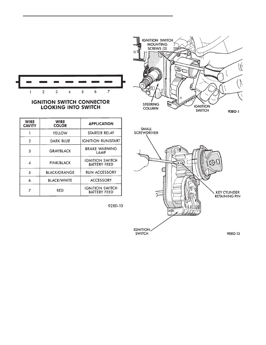
(4) Remove ignition switch mounting screws. Use

tamper proof torx bit Snap-on TTXR15A2, TTXR20A2
or equivalent to remove the screws (Fig. 1).

(5) Gently pull switch away from the column. Release

connector locks on the 7 terminal wiring connector,
then remove the connector from the ignition switch.

(6) Release connector lock on the 4 terminal con-

nector, then remove the connector from the ignition
switch.

(7) To remove the key cylinder from the ignition

switch:

(a) Insert key in the ignition switch. Turn the

key to the LOCK position. Using a small screw-
driver, depress the key cylinder retaining pin until
it is flush with the key cylinder surface (Fig. 2).

(b) Rotate the key clockwise to the OFF position.

The key cylinder will unseat from the ignition
switch (Fig. 3). When the key cylinder is unseated,
it will be approximately 1/8 inch away from the ig-
nition switch halo light ring. Do not attempt to
remove the key cylinder at this time.

(c) With the key cylinder in the unseated posi-

tion, rotate the key counterclockwise to the lock po-
sition and remove the key.

(d) Remove key cylinder from ignition switch

(Fig. 4).

INSTALLATION

If the vehicle has a floor mounted gear shifter,

place the selector in the Park position.

IGNITION SWITCH DESIGNATIONS

Fig. 1 Ignition Switch Screw Removal

Fig. 2 Key Cylinder Retaining Pin

Ä

IGNITION SYSTEMS

8D - 45

(1) Connect electrical connectors to the ignition

switch. Make sure that the switch locking tabs are fully
seated in the wiring connectors.

(2) Before attaching the ignition switch to a tilt

steering column, the transaxle shifter must be in the
Park position. Also the park lock dowel pin and the
column lock flag must be properly indexed before
installing the switch (Fig. 5).

(a) Place the transaxle shifter in the PARK posi-

tion.

(b) Place the ignition switch in the lock position.

The switch is in the lock position when the column
lock flag is parallel to the ignition switch terminals
(Fig. 5).

(c) Position ignition switch park lock dowel pin so

it will engage the steering column park lock slider
linkage (Fig. 6).

(d) Apply a light coating of grease to the column

lock flag and the park lock dowel pin.
(3) Place the ignition switch against the lock hous-

ing opening on the steering column. Ensure ignition
switch park lock dowel pin enters the slot in the park
lock slider linkage in the steering column.

(4) Install ignition switch mounting screws. Tighten

screws to 2 N

Im (17 in. lbs.) torque.

(5) Install steering column covers. Tighten screws to

2 N

Im (17 in. lbs.) torque.

(6) If the vehicle is equipped with a tilt steering

column, install the tilt lever.

(7) To install the ignition key in the lock cylinder:

(a) With the key cylinder and the ignition switch

in the Lock position, insert the key cylinder into the
ignition switch until it bottoms.

(b) Insert ignition key into lock cylinder. While

gently pushing the key cylinder in toward the igni-
tion switch, rotate the ignition key until to the end of
travel.

(c) Connect negative cable to battery.

(8) Check for proper operation of the halo light, shift

lock (if applicable), and column lock. Also check for
proper operation of the ignition switch accessory, lock,
off, run, and start positions.

Fig. 3 Unseated Key Cylinder

Fig. 4 Key Cylinder Removal

Fig. 5 Ignition Switch View From Column

Fig. 6 Ignition Switch Mounting Pad

8D - 46

IGNITION SYSTEMS

Ä

SPECIFICATIONS

GENERAL INFORMATION

The following specifications are published from the

latest information available at the time of publica-
tion. If anything differs from the specifications on the
Vehicle Emission Control Information Label, use the
specifications on the label.

SPARK PLUG WIRE ROUTING—2.2L TBI, 2.5L

TBI AND 2.5L MPI ENGINES

SPARK PLUG WIRE ROUTING—

TURBO III ENGINE

SPARK PLUG WIRE ROUTING—3.0L ENGINE

SPARK PLUG WIRE ROUTING—3.3L AND

3.8L ENGINES

Ä

IGNITION SYSTEMS

8D - 47

3.3L/3.8L ENGINE DIRECT IGNITION SYSTEM

DISTRIBUTORS

8D - 48

IGNITION SYSTEMS

Ä


Content   ..  294  295  296  297   ..