Chrysler Le Baron, Dodge Dynasty, Plymouth Acclaim. Manual - part 277
GENERATOR
INDEX
page
page
General Information
. . . . . . . . . . . . . . . . . . . . . . . . 9
Generator Replacement—2.2L Turbo Engine
(With 16 Valve Cylinder Head)
. . . . . . . . . . . . . 10
Generator Replacement—2.2L/2.5L Engine
. . . . . . 9
Generator Replacement—3.0L Engine
. . . . . . . . . 10
Generator Replacement—3.3L/3.8L Engine
. . . . . 11
GENERAL INFORMATION
This section will cover generator removal and instal-
lation only. Information covering generator on-vehicle
testing and diagnosis can be found in Group 8A,
Battery/Starting/Charging Systems Diagnostics. To
identify the generator, refer to the Generator Specifi-
cation chart at the rear of this section.
These generators are not intended to be disas-
sembled for service. It must be replaced as an
assembly.
GENERATOR REPLACEMENT—2.2L/2.5L ENGINE
Removal and repositioning of A/C compressor (with-
out disconnecting refrigerant lines) is necessary on
some models to gain access to generator.
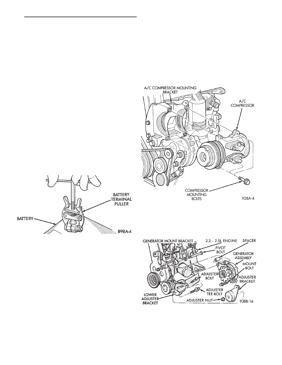
(1) Disconnect battery negative cable (Fig. 1).
(2) If Equipped With Air Conditioning:
(a) Remove the A/C drive belt. Refer to Group 7,
Cooling System.
(b) Remove the four bolts retaining the A/C com-
pressor to the mounting bracket (Fig. 2).
(c) Without disconnecting the A/C refrigerant
lines, position the A/C compressor to allow generator
removal.
WARNING: THE A/C REFRIGERANT SYSTEM IS UN-
DER PRESSURE EVEN WHEN THE ENGINE IS OFF.
REFER TO THE SAFETY PRECAUTIONS AND WARN-
INGS SECTION IN HEATING AND A/C, GROUP 24,
BEFORE PERFORMING ANY SERVICE OPERATION.
(3) Remove the generator drive belt. Refer to Group
7, Cooling System.
(4) Remove the two generator mounting bolts (Fig.
3) and position the generator to gain access to all the
wire connectors. If equipped with:
• BOSCH GENERATOR: Remove B+ terminal nut,
field terminal nuts, and ground harness hold down
nuts (Fig. 4). Remove wire connector assembly.
• NIPPONDENSO GENERATOR: Remove nuts
from field terminals, ground terminal, wire harness
Fig. 1 Remove Battery Negative (-) Cable
Fig. 2 A/C Compressor Replacement—2.2 L/2.5 L
Engine
Fig. 3 Remove/Install Generator
Ä
BATTERY/STARTER/GENERATOR SERVICE
8B - 9