Chrysler Le Baron, Dodge Dynasty, Plymouth Acclaim. Manual - part 275


  Index      Chrysler     Chrysler Le Baron, Dodge Dynasty, Plymouth Acclaim - service repair manual 1993 year


Search            


Content   ..  273  274  275  276   ..


Chrysler Le Baron, Dodge Dynasty, Plymouth Acclaim. Manual - part 275


BATTERY/STARTER/GENERATOR SERVICE

CONTENTS

page

page

BATTERY REMOVAL, INSTALLATION AND

SERVICE

. . . . . . . . . . . . . . . . . . . . . . . . . . . . . 1

GENERATOR

. . . . . . . . . . . . . . . . . . . . . . . . . . . . 9

SPECIFICATIONS

. . . . . . . . . . . . . . . . . . . . . . . 12

STARTER . . . . . . . . . . . . . . . . . . . . . . . . . . . . . . . 4

BATTERY REMOVAL, INSTALLATION AND SERVICE

GENERAL INFORMATION

This first section will cover Battery replacement and

service procedures only. For Battery diagnostic proce-
dures, refer to Group 8A, Battery/Starting/Charging
Systems Diagnostics.

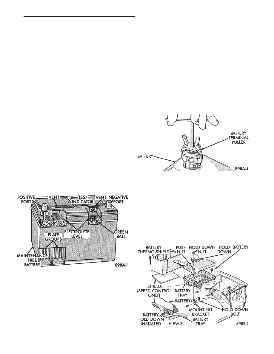
Factory installed batteries (Fig. 1) do not have re-

movable battery cell caps. Water cannot be added to
factory installed battery. Battery is sealed, except for
small vent holes in the top. Chemical composition
inside the battery produces an extremely small amount
of gases at normal charging voltages. The factory
installed battery is equipped with a test indicator that
displays a colored ball to show the battery’s state of
charge.

• Green Indicator = Full charge

• Black Indicator = Discharged

• Yellow Indicator = Battery replacement required.

BATTERY VISUAL INSPECTION AND SERVICE

(1) Make sure ignition switch is in OFF position and

all accessories are OFF.

(2) Disconnect and remove the battery cable termi-

nals from the battery posts. Remove negative cable
first (Fig. 2).

WARNING: TO PROTECT THE HANDS FROM BAT-
TERY ACID, A SUITABLE PAIR OF HEAVY DUTY
RUBBER GLOVES, NOT THE HOUSEHOLD TYPE,
SHOULD BE WORN WHEN REMOVING OR SERVIC-
ING A BATTERY. SAFETY GLASSES ALSO SHOULD
BE WORN.

(3) Lift battery heat shield off battery, if equipped

(Fig. 3).

(4) Remove battery hold down nut and clamp.

Fig. 1 Maintenance Free Battery

Fig. 2 Remove Battery Cables

Fig. 3 Battery Hold-Down

Ä

BATTERY/STARTER/GENERATOR SERVICE

8B - 1

(5) Remove the battery from vehicle.
(6) Clean top of battery with a solution of warm

water and baking soda. Apply solution with a bristle
brush and allow to soak until acid deposits loosen
(Fig. 4). Rinse with clear water and blot dry with pa-
per toweling. Dispose of toweling in a safe manner.
Refer to the WARNINGS on the top of battery.

CAUTION: Do not allow baking soda solution to en-
ter vent holes, as damage to battery can result.

(7) Inspect battery case and cover for cracks or

leakage. If leakage is present, battery must be re-
placed.

(8) Inspect battery tray (Fig. 5) for damage caused

by acid from battery. If acid damage is present, it
will be necessary to clean area with same solution
described in Step (6).

(9) Clean battery posts with a suitable battery post

cleaning tool (Fig. 6).

(10) Clean inside surfaces of battery cable terminal

clamps with a suitable battery terminal cleaning tool
(Fig. 7). Replace damaged or frayed cables and bro-
ken terminal clamps.

(11) Inspect battery for proper or damaged hold

down ledge.

(12) Install battery in vehicle making sure that

battery is positioned properly on battery tray (Fig.
3).

(13) Install battery hold down clamp and nut. Be

sure that clamp is positioned properly and aligned on
battery.

(14) Install battery heat shield.
(15) Place felt grease washer onto Positive (+) bat-

tery post.

(16) Connect battery cable clamps to battery posts

making sure top of clamp is flush with top of post
(Fig. 8). Install POSITIVE cable first.

(17) Tighten clamp nuts securely.

Fig. 4 Cleaning Battery

Fig. 5 Battery Tray

Fig. 6 Cleaning Battery Posts

8B - 2

BATTERY/STARTER/GENERATOR SERVICE

Ä

Fig. 7 Cleaning Battery Cable Terminal

Fig. 8 Battery Cables Disconnected

Ä

BATTERY/STARTER/GENERATOR SERVICE

8B - 3

STARTER

INDEX

page

page

General Information

. . . . . . . . . . . . . . . . . . . . . . . . 4

Neutral Starter and Back-Up Switch

. . . . . . . . . . . 8

Starter Component Replacement

. . . . . . . . . . . . . . 5

Starter Interlock Switch: Clutch Pedal Mounted/

Manual Transmission Only

. . . . . . . . . . . . . . . . . 7

Starter Motor Replacement

. . . . . . . . . . . . . . . . . . 4

Starting System

. . . . . . . . . . . . . . . . . . . . . . . . . . . 4

Supply Circuit and Control Circuit

. . . . . . . . . . . . . 4

GENERAL INFORMATION

This section will cover Starter replacement and

service procedures only. For starter diagnostic proce-
dures, refer to Group 8A, Battery/Starting/Charging
Systems Diagnostics.

STARTING SYSTEM

The starting system has:

• Ignition switch

• Starter relay

• Neutral starting and back-up switch with auto-
matic transmissions
• Clutch pedal mounted starter interlock switch
with manual transmissions
• Wiring harness

• Battery

• Starter motor with an integral solenoid

BOSCH STARTERS

• A Bosch permanent magnet starter motor is avail-
able on 2.2L, 2.5L and 3.0L engines on all vehicles.
A planetary gear train transmits power between
starter motor and pinion shaft. The fields consist of
six permanent magnets.

NIPPONDENSO STARTERS

• A Nippondenso reduction gear-field coil starter
motor is available on 3.0L, 3.3L and 3.8L engines.

SUPPLY CIRCUIT AND CONTROL CIRCUIT

Both starter systems consist of two separate cir-

cuits:
• A high amperage supply to feed the starter motor.

• A low amperage circuit to control the starter sole-
noid.

For additional information on starter motor supply

and control circuits, refer to Group 8A, Battery/Start-
ing/Charging Systems Diagnostics.

STARTER MOTOR REPLACEMENT

BOSCH STARTER—2.2L/2.5L ENGINE

(1) Disconnect battery negative cable (Fig. 1).
(2) Raise vehicle.

(3) Remove heat shield clip from the starter and

heat shield is clipped to starter (Fig. 2). For easier
servicing, do not remove the wiring from starter at
this time.

(4) Remove two bolts and one nut attaching starter

to engine (Fig. 3).

(5) Remove starter/starter solenoid assembly from

engine. Position the starter to gain access to the wir-
ing connectors.

(6) Disconnect the positive battery cable and wir-

ing at the starter.

(7) Remove the starter from vehicle.

Fig. 1 Remove or Install Battery Cable

Fig. 2 Starter Heat Shield—4 Cylinder Engines

8B - 4

BATTERY/STARTER/GENERATOR SERVICE

Ä


Content   ..  273  274  275  276   ..