Chrysler Le Baron, Dodge Dynasty, Plymouth Acclaim. Manual - part 264
TESTING SYSTEM FOR LEAKS
With engine not running, wipe the radiator filler
neck sealing seat clean. The radiator should be full.
Attach a radiator pressure tester to the radiator, as
shown in (Fig. 4) and apply 104 kPa (15 psi) pres-
sure. If the pressure drops more than 2 psi in 2 min-
utes inspect all points for external leaks.
All hoses, radiator and heater, should be moved
while at 15 psi since some leaks occur while driving
due to engine rock, etc.
If there are no external leaks after the gauge dial
shows a drop in pressure, detach the tester. Start en-
gine and run the engine to normal operating temper-
ature in order to open the thermostat and allow the
coolant to expand. Re-attach the tester. If the needle
on the dial fluctuates it indicates a combustion leak,
usually a head gasket leak.
WARNING:
WITH
TOOL
IN
PLACE
PRESSURE
BUILDS UP FAST. ANY EXCESSIVE AMOUNT OF
PRESSURE BUILT UP BY CONTINUOUS ENGINE
OPERATION MUST BE RELEASED TO A SAFE
PRESSURE POINT. NEVER PERMIT PRESSURE TO
EXCEED 138 KPA (20 PSI).
If the needle on the dial does not fluctuate, race
the engine a few times. If an abnormal amount of
coolant or steam is emitted from the tail pipe, it may
indicate a faulty head gasket, cracked engine block
or cylinder head.
There may be internal leaks which can be deter-
mined by removing the oil dip-stick. If water glob-
ules appear intermixed with the oil it will indicate a
internal leak in the engine. If there is an internal
leak, the engine must be disassembled for repair.
COOLANT RECOVERY SYSTEM (CRS)
This system works in conjunction with the radiator
pressure cap to utilize thermal expansion and con-
traction of the coolant to keep the coolant free of
trapped air. It provides a volume for expansion and
contraction, provides a convenient and safe method
for checking coolant level and adjusting level at at-
mospheric pressure without removing the radiator
pressure cap. It also provides some reserve coolant to
cover minor leaks and evaporation or boiling losses.
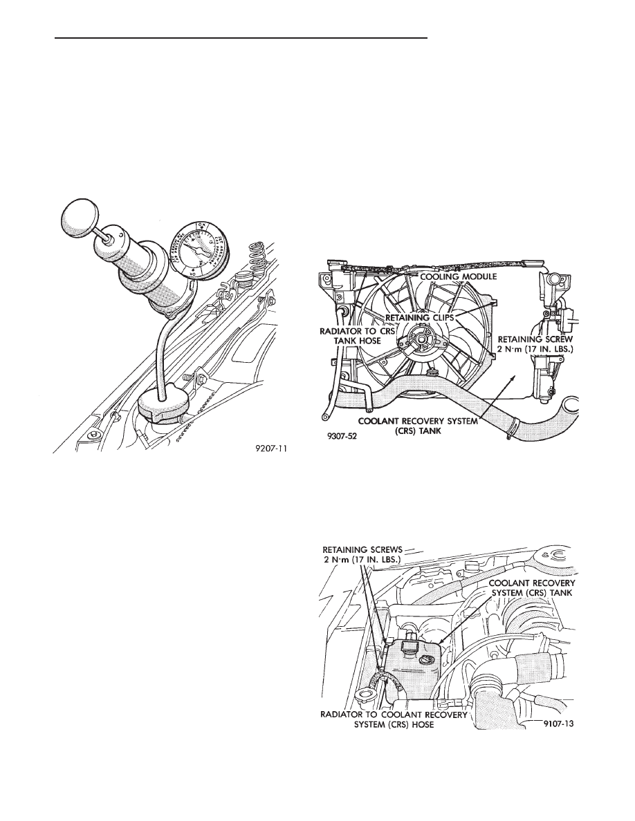
All vehicles are equipped with this system (Figs. 5
and 6).
See Coolant Level Check Service, Deaeration and
Pressure Cap sections for operation and service. Ve-
hicles equipped with the electric monitor system use
a level sensor in the CRS tank, see Group 8E Elec-
trical for service.
Fig. 4 Pressure Testing Cooling System
Fig. 5 Coolant Recovery System Typical
Fig. 6 Coolant Recovery System—AC-AY Models
Ä
COOLING SYSTEM
7 - 17