Chrysler Le Baron, Dodge Dynasty, Plymouth Acclaim. Manual - part 262


  Index      Chrysler     Chrysler Le Baron, Dodge Dynasty, Plymouth Acclaim - service repair manual 1993 year


Search            


Content   ..  260  261  262  263   ..


Chrysler Le Baron, Dodge Dynasty, Plymouth Acclaim. Manual - part 262


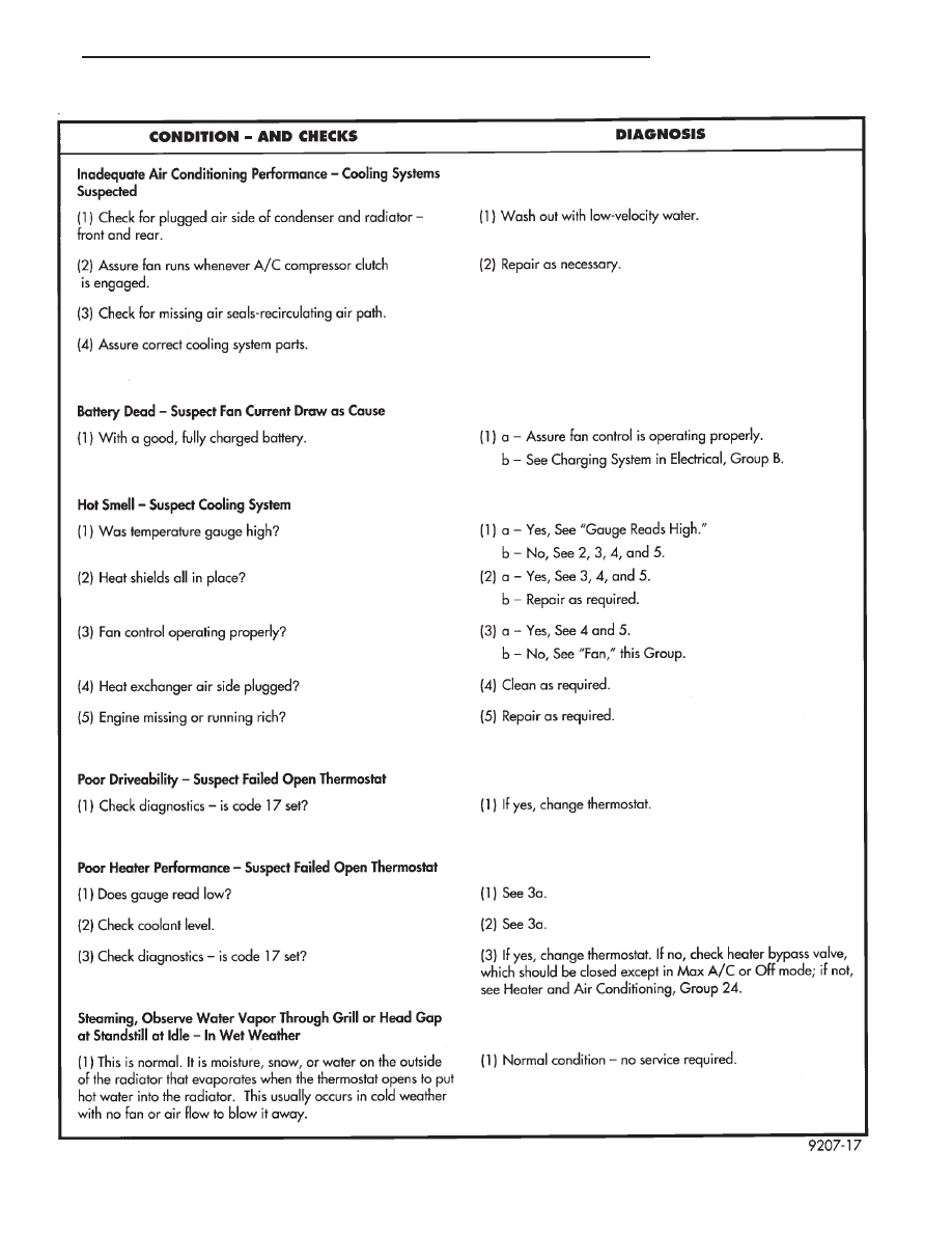
COOLING SYSTEM DIAGNOSIS

Ä

COOLING SYSTEM

7 - 9

SERVICE PROCEDURES

INDEX

page

page

Automatic Transmission Oil Coolers

. . . . . . . . . . 23

Coolant

. . . . . . . . . . . . . . . . . . . . . . . . . . . . . . . . 14

Coolant Recovery System (CRS)

. . . . . . . . . . . . . 17

Cooling System Drain, Clean, Flush and Refill

. . 15

Electric Fan Motor

. . . . . . . . . . . . . . . . . . . . . . . . 22

Engine Thermostats

. . . . . . . . . . . . . . . . . . . . . . . 13

Fan Shroud

. . . . . . . . . . . . . . . . . . . . . . . . . . . . . 23

Fans

. . . . . . . . . . . . . . . . . . . . . . . . . . . . . . . . . . 21

Radiator Hoses

. . . . . . . . . . . . . . . . . . . . . . . . . . 21

Radiator Pressure Cap

. . . . . . . . . . . . . . . . . . . . 18

Radiators

. . . . . . . . . . . . . . . . . . . . . . . . . . . . . . . 18

Testing System for Leaks

. . . . . . . . . . . . . . . . . . 17

Water Pumps

. . . . . . . . . . . . . . . . . . . . . . . . . . . 10

WATER PUMPS

A quick test to tell whether or not the pump is

working is to see if the heater warms properly. A
defective pump will not be able to circulate heated
coolant through the long heater hose.

The water pump on all models can be replaced

without discharging the air conditioning system.

WATER PUMP—2.2/2.5L ENGINE

The 2.2/2.5L engine water pump has a diecast alu-

minum body and housing with a stamped steel impel-
ler. The 2.2/2.5L pump uses an O-ring gasket between
body and housing. The assembly bolts directly to the
block. Cylinder block to water pump sealing is provided
by a rubber O-ring.

REMOVAL

(1) Drain cooling system. Refer to Draining Cooling

System in this group.

(2) If equipped with air conditioning, see Solid

Mount Accessory Bracket in (Standard Service Proce-
dures) Group 9, Engine:

(a) Remove air conditioning compressor and gen-

erator from solid mount bracket and set aside.It is
not necessary to discharge the a/c system.

(b) Remove solid mount bracket.

(3) If the vehicle is not equipped with air condi-

tioning, remove generator and mounting bracket.

(4) Disconnect lower radiator and heater hoses

from pump.

(5) Remove water pump attaching screws to engine

(Fig. 1). Turbo III has a spacer between the water
pump and block on the lower screw.

DISASSEMBLY

(1) Remove three screws holding pulley to water

pump.

(2) Remove nine screws holding water pump body

to housing. Remove the pump body from housing
(Fig. 2).

(3) Clean gasket surfaces on water pump housing

and engine block.

(4) Remove and discard O-ring gaskets and clean

O-ring grooves.

Fig. 2 Water Pump Components—2.2/2.5L

Fig. 1 Water Pump—2.2/2.5L Engines

7 - 10

COOLING SYSTEM

Ä

INSPECTION

Replace water pump body assembly if it has any of

these defects:

(1) Cracks or damage on the body.
(2) Water leaks from the shaft seal, evident by

coolant traces below the vent hole.

(3) Loose or rough turning bearing.
(4) Impeller rubs either the pump body or the hous-

ing.

ASSEMBLY

Body assembly and housing are serviced as separate

components.

(1) Install new O-ring gasket in body O-ring groove.
(2) Assemble pump body to housing and tighten nine

screws to 12 N

Im (105 in. lbs.) (Fig. 2).

(3) Rotate pump by hand to check for freedom of

movement.

(4) Position water pump pulley to water pump.In-

stall three screws and tighten to 30 N

Im (250 in. lbs.).

(5) Position new O-ring in housing to block O-ring

groove.

INSTALLATION

(1) On Turbo III engines install the coolant deflector

into the block before installing pump on engine (Fig. 3).
Install spacer between the pump and block for
Turbo III only before tightening pump to speci-
fications. 
Tighten three top screws (Fig. 1) to 28 N

Im

(250 in. lbs.) and lower screw to 68 N

Im (50 ft. lbs.).

(2) Install bypass/heater hose and lower radiator

hose.

(3) Install generator and air conditioning compres-

sor bracket(s). For solid mount bracket see standard
service procedures in Group 9 Engine.

(4) Install generator and air conditioning compres-

sor.

(5) Refill cooling system. See Refilling Cooling

System.

(6) Install drive belt, See Accessory Drive Belts,

this Group.

WATER PUMP—3.0L ENGINE

The 3.0L pump bolts directly to the engine block,

using a gasket for pump to block sealing (Fig. 4). The
pump is serviced as a unit.

The water pump is driven by the timing belt. See

Timing System in Group 9, Engine for component re-
moval providing access to water pump.

REMOVAL

(1) Drain cooling system. Refer to Draining Cool-

ing System in this group.

(2) Remove mounting bolts.
(3) Separate pump from water inlet pipe (Figs. 4

and 5) and remove.

INSPECTION

Replace the water pump if it has any of the follow-

ing defects.

Fig. 4 Water Pump—3.0L Engine

Fig. 5 Water Pump Inspection

Fig. 3 Coolant Deflector—Turbo III

Ä

COOLING SYSTEM

7 - 11

(1) Damage or cracks on the pump body.
(2) Coolant leaks, if the shaft seal is leaking, evi-

dent by traces of coolant leaks from vent hole A in
(Fig. 5).

(3) Impeller rubs inside of pump.
(4) Excessively loose or rough turning bearing.

INSTALLATION

(1) Clean all gasket and O-ring surfaces on pump

and water pipe inlet tube.

(2) Install new O-ring on water inlet pipe (Fig. 6).

Wet the O-ring with water to facilitate assembly.

CAUTION: Keep the O-ring free of oil or grease.

(3) Install new gasket on water pump and install

pump inlet opening over water pipe, press assembly
to cause water pipe insertion into pump housing.

(4) Install pump to block mounting bolts and

tighten to 27 N

Im (20 ft. lbs.).

(5) See Timing System in Engine, Group 9 and in-

stall timing belt. Reassemble engine.

(6) Fill cooling system. See Refilling Cooling Sys-

tem.

WATER PUMP—3.3L AND 3.8L ENGINES

The pump has a die cast aluminum body and a

stamped steel impeller. It bolts directly to the chain
case cover, using an O-ring for sealing. It is driven
by the back surface of the Poly-V Drive Belt.

REMOVAL

(1) Drain Cooling System. Refer to Draining Cool-

ing System in this group.

(2) Remove Poly V Drive Belt.
(3) Remove right front lower fender shield.
(4) Remove pump pulley bolts and remove pulley.
(5) Remove pump mounting screws (Fig. 7). Re-

move pump.

(6) Remove and discard O-ring seal.

(7) Clean O-ring groove and O-ring surfaces on

pump and chain case cover. Take care not to scratch
or gouge sealing surface.

INSPECTION

Replace the water pump if it has any of the follow-

ing defects.

(1) Damage or cracks on the pump body.
(2) Coolant leaks; if the seal is leaking, evident by

traces of coolant leaks from vent hole.

(3) Loose or rough turning bearing.
(4) Impeller rubs either the pump body or chain-

case cover.

INSTALLATION

(1) Install new O-ring in O-ring groove (Fig. 8).
(2) Install pump to chain case cover. Torque screws

to 12 N

Im (105 in. lbs.).

(3) Rotate pump by hand to check for freedom of

movement.

(4) Position pulley on pump. Install screws and

torque to 30 N

Im (250 in. lbs.).

Fig. 6 Water Pipe O-Ring

Fig. 7 Water Pump—3.3L and 3.8L Engines

Fig. 8 Water Pump Body

7 - 12

COOLING SYSTEM

Ä


Content   ..  260  261  262  263   ..