Chrysler Le Baron, Dodge Dynasty, Plymouth Acclaim. Manual - part 260
COOLING SYSTEM
CONTENTS
page
page
ACCESSORY DRIVE BELTS
. . . . . . . . . . . . . . . 24
ENGINE BLOCK HEATER
. . . . . . . . . . . . . . . . . 28
GENERAL INFORMATION . . . . . . . . . . . . . . . . . . 1
SERVICE PROCEDURES
. . . . . . . . . . . . . . . . . . 10
SPECIFICATIONS
. . . . . . . . . . . . . . . . . . . . . . . 29
GENERAL INFORMATION
Throughout this group, references may be made to
a particular vehicle by letter or number designation.
A chart showing the breakdown of these designations
is included in the Introduction Section at the front of
this service manual.
COOLING SYSTEM
The cooling system consists of an engine cooling
module, thermostat, coolant, a water pump to circu-
late the coolant. The engine cooling module may con-
sist of a radiator, electric fan motor, shroud, radiator
pressure cap, coolant reserve system, transmission oil
cooler, hoses, clamps, air condition condenser, trans-
mission oil lines and charge air cooler.
• When Engine is cold: Thermostat is closed, cooling
system has no flow through the radiator. The coolant
bypass flows through the engine only.
• When Engine is warm: Thermostat is open, cooling
system has bypass flow and coolant flow through ra-
diator.
Its primary purpose is to maintain engine temper-
ature in a range that will provide satisfactory engine
performance and emission levels under all expected
driving conditions. It also provides hot water (cool-
ant) for heater performance and cooling for auto-
matic transmission oil. It does this by transferring
heat from engine metal to coolant, moving this
heated coolant to the radiator, and then transferring
this heat to the ambient air.
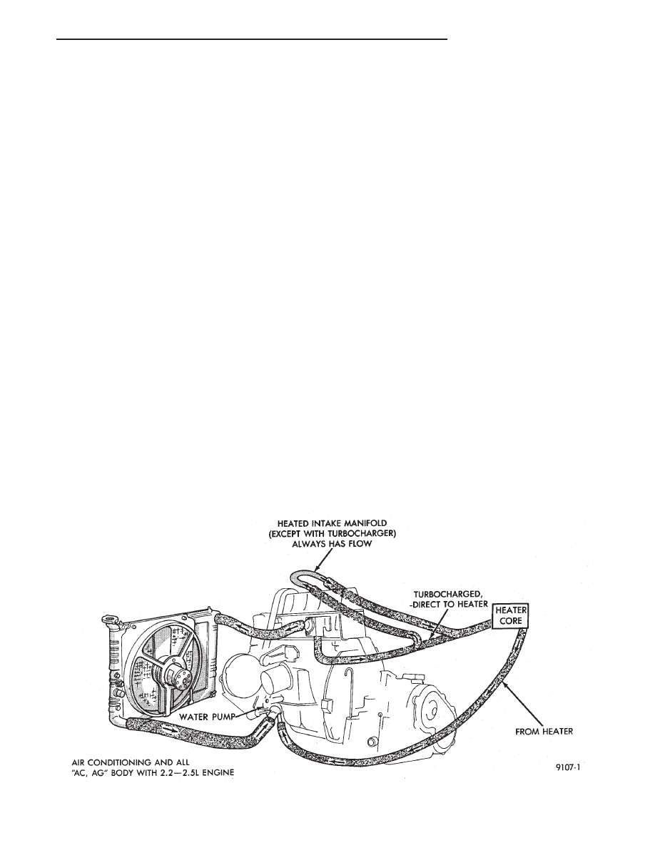
Coolant flow circuits for 2.2L and 2.5L engine
equipped vehicles are shown in (Fig 1). Turbocharged
equipped engines coolant routing and plumbing are
shown in (Fig 2). The 3.0L engine coolant routing is
shown in (Fig 3). The 3.3L and 3.8L engine coolant
routing is shown in (Fig 5).
Fig. 1 Cooling System Operation—2.2/2.5L Engines
Ä
COOLING SYSTEM
7 - 1