Index Chrysler Chrysler Le Baron, Dodge Dynasty, Plymouth Acclaim - service repair manual 1993 year
Search
Content .. 256 257 258 259 ..
Chrysler Le Baron, Dodge Dynasty, Plymouth Acclaim. Manual - part 258
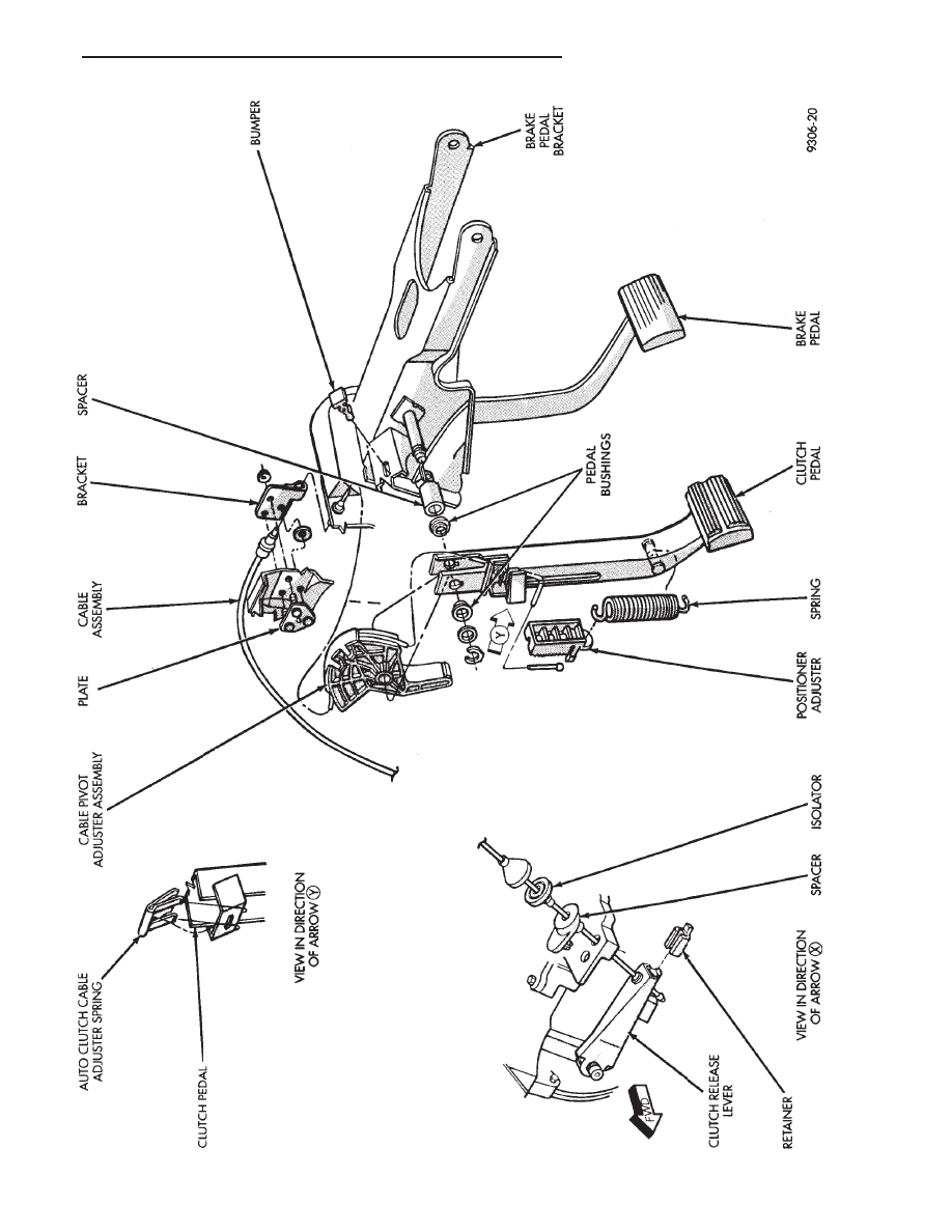
Fig.
2
Self-Adjusting
Clutch
Release
Mechanism
Ä
MANUAL TRANSAXLE CLUTCH
6 - 3