Chrysler Le Baron, Dodge Dynasty, Plymouth Acclaim. Manual - part 256
(10) Install battery on battery tray and install and
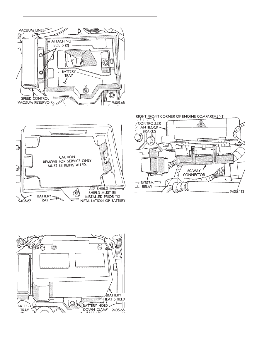
securely tighten the battery hold down clamp (Fig.
13). Then install heat shield, on battery (Fig. 13).
(11) Install battery cables on battery. Securely
tighten clamping bolts on battery cable terminals.
(12) Reset any electrical components of the vehicle
which were affected by the removal of the battery.
(13) Road test vehicle to verify correct operation of
the vehicles’s base and Antilock brake systems.
ELECTRONIC COMPONENTS
CONTROLLER ANTILOCK BRAKE CAB
REMOVE
(1) Turn vehicle ignition off.
(2) Disconnect the wiring harness connector from
the Antilock system relay (Fig. 1). Relay will be re-
moved as part of the CAB bracket.
CAUTION: BEFORE REMOVING 60 WAY CONNEC-
TOR FROM THE CAB VERIFY THAT THE VEHICLE’S
IGNITION IS IN THE OFF OR LOCK POSITION. IF IG-
NITION IS ON WHEN 60 WAY CONNECTOR IS RE-
MOVED
FROM
THE
CAB
DAMAGE
TO
THE
CONTROLLER COULD OCCUR.
(3) Loosen bolt (Fig. 2) retaining the wiring har-
ness 60 way connector to the CAB. Then disconnect
the 60 way connector (Fig. 2) from the CAB by pull-
ing it straight out, do not twist connector when re-
moving.
(4) Remove the 2 bolts (Fig. 3) attaching the CAB
module mounting bracket, to the frame rail of the ve-
hicle.
(5) Remove the CAB and its mounting bracket as
an assembly from the vehicle from the vehicle.
(6) Remove the 3 screws (Fig. 4) attaching the
CAB to the CAB mounting bracket. Then separate
CAB from mounting bracket.
Fig. 11 Vacuum Reservoir Installation And
Attaching Bolts
Fig. 12 Battery Tray Access Shield Installed
Fig. 13 Battery Hold Down Clamp And Heat Shield
Installed
Fig. 1 CAB Location
Ä
ANTILOCK 4 BRAKE SYSTEM
5 - 41