Chrysler Le Baron, Dodge Dynasty, Plymouth Acclaim. Manual - part 255
Antilock 4 Brake System in this service manual
supplement for required bleeding procedure.
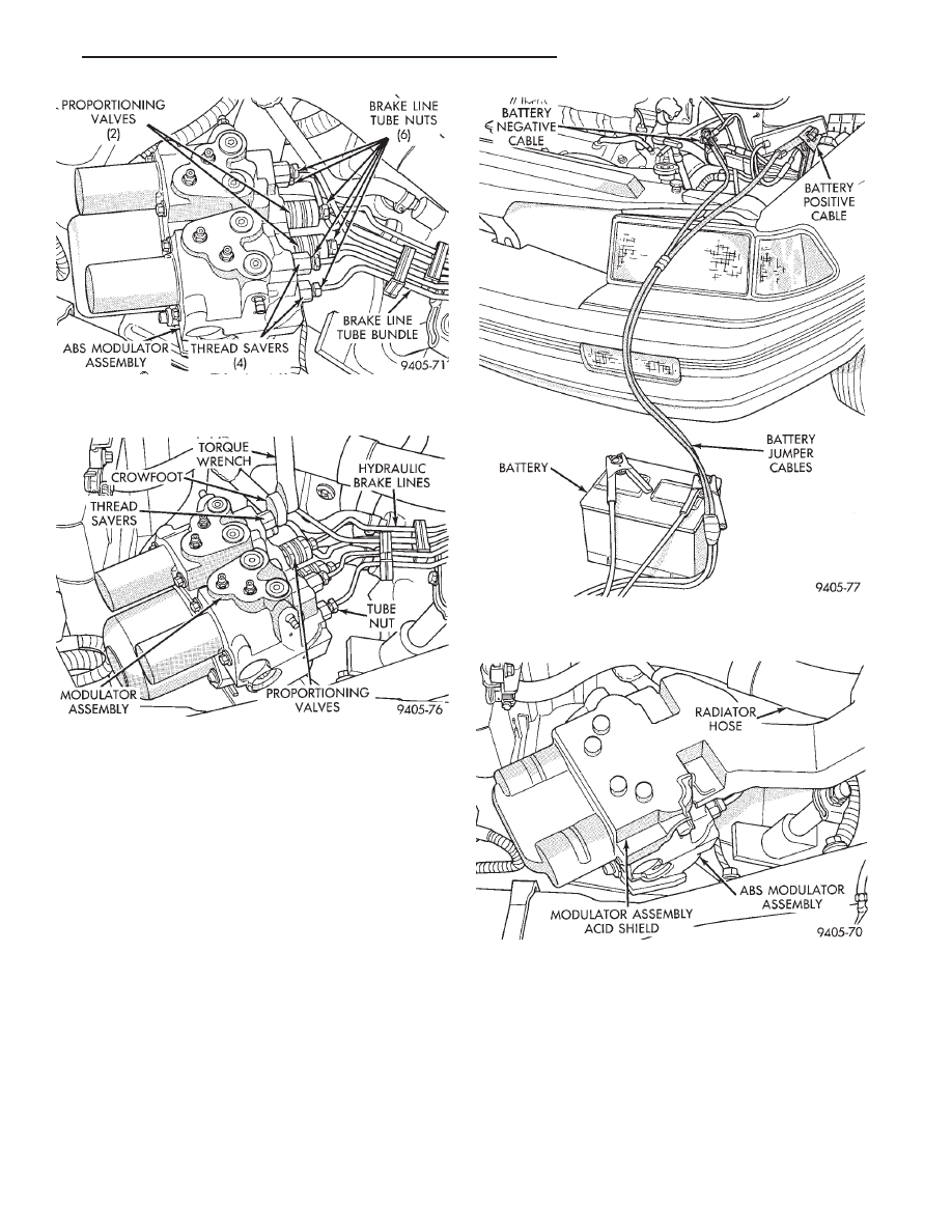
(9) Install battery acid shield (Fig. 14) onto the ABS
modulator assembly. Be sure acid shield is securely
attached to modulator assembly before installing
battery tray.
(10) Install battery tray into vehicle. Then install
the 4 bolts (Fig. 15) attaching battery tray to inner
fender and frame rail. Torque the 4 battery tray attach-
ing bolts to 20 N
Im (175 in.lbs.).
(11) If equipped, install speed control vacuum reser-
voir on battery tray. Install the 2 speed control vacuum
reservoir attaching bolts (Fig. 16). Torque the 2
vacuum reservoir attaching bolts to 4 N
Im (30 in. lbs.).
(12) Install battery tray access cover (Fig. 17) on
bottom of battery tray. The access cover MUST be
on battery tray, before battery is installed.
(13) Install battery on battery tray. Then install
and securely tighten the battery hold down clamp
(Fig. 18). Then install battery heat shield, on battery
(Fig. 18).
(14) Install battery cables on battery. Securely
tighten clamping bolts on battery cable terminals.
(15) Reset any electrical components of the vehicle
which were affected by the removal of the battery.
(16) Road test vehicle to verify correct operation of
the vehicles’s base and Antilock brake systems.
Fig. 13 Battery Connected To Vehicle For Bleeding
Modulator Assembly
Fig. 14 Modulator Assembly Acid Shield Installed
Fig. 11 Hydraulic Brake Line Connections at
Modulator Assembly
Fig. 12 Torquing Brake Line Connections To
Modulator Assembly
Ä
ANTILOCK 4 BRAKE SYSTEM
5 - 37