Chrysler Le Baron, Dodge Dynasty, Plymouth Acclaim. Manual - part 241


  Index      Chrysler     Chrysler Le Baron, Dodge Dynasty, Plymouth Acclaim - service repair manual 1993 year


Search            


Content   ..  239  240  241  242   ..


Chrysler Le Baron, Dodge Dynasty, Plymouth Acclaim. Manual - part 241


HYDRAULIC SPRING ACCUMULATOR

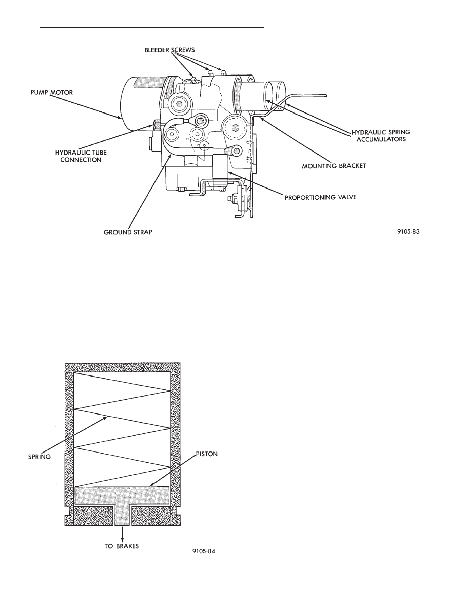
The Hydraulic Spring Accumulators (Fig. 2) (one

on each circuit) are used to store pressurized hydrau-
lic brake fluid during ABS operation only. This fluid
is used during hard braking when the ABS system is
activated, to supplement brake pressure when re-
quired. During normal Non ABS braking operation
there is NO pressurized brake fluid stored in the ac-
cumulators. The Hydraulic Spring Accumulators are
not a serviceable part of the Modulator Assembly
and should never be removed from the assembly.

PRESSURE DIFFERENTIAL VALVE/SWITCH
(DELTA P SWITCH)

The Pressure Differential Valve/Switch is located

inside the hydraulic assembly. This valve/switch func-
tions

the

same

as

the

Pressure

Differential

Valve/Switch located in the combination valve on stan-
dard brake systems. The delta P switch monitors the
primary and secondary hydraulic circuits for a differ-
ence in pressure. A pressure difference greater than
225 psi. Will move and latch the shuttle to ground the
Red Brake Warning Light circuit. This will in turn,
turn on the Red Brake Warning Light in the instru-
ment panel to warn the driver of a hydraulic system
problem. This Pressure Differential Valve Switch is a
replaceable item of the Modulator Assembly. The Red
Brake Warning Light indicates a problem with
the foundation brake system and not the Anti-
Lock system.

PUMP/MOTOR ASSEMBLY

The Modulator Assembly contains 2 Pump Assem-

blies, one each for the primary and secondary hydrau-
lic circuits. Both pumps are driven by a common
electric motor which is part of the Modulator Assembly.
The pumps pick up fluid from the sumps to supply
pressure to the accumulators or hydraulic system via
the isolation valves during an Anti-Lock stop. The
motor only runs during an ABS stop and is controlled
by the (CAB) via the Pump/Motor Relay. The
Pump/Motor Assembly is not a serviceable item. If it
requires service the Modulator Assembly must be re-
placed.

Fig. 1 Modulator Assembly

Fig. 2 Hydraulic Spring Accumulator

Ä

ANTI-LOCK 6 BRAKE SYSTEM

5 - 117

PROPORTIONING VALVES

Two Proportioning Valves (Fig. 3) are used in the

system, one for each rear brake hydraulic circuit.
The Proportioning Valves function the same as in a
standard brake system. The Proportioning Valves are
located on the bottom of the hydraulic assembly (Fig.
1). They are the same screw in type as the ones used
on the Bendix Anti-Lock 10 and Bosh Anti-Lock
Brake systems.

WHEEL SPEED SENSORS

One Wheel Speed Sensor (WSS), is located at each

wheel (Fig. 4 and 5), and sends a small (AC) signal
to the control module (CAB). This signal is generated
by magnetic induction. The magnetic induction is
created, when a toothed sensor ring Tone Wheel (Fig.
6) passes a stationary magnetic Wheel Speed Sensor.
The (CAB) converts the (AC) signal generated at
each wheel into a digital signal. If a wheel locking
tendency is detected, the (CAB) will then modulate
hydraulic pressure to prevent the wheel(s) from lock-
ing.

The front Wheel Speed Sensor is attached to a boss

in the steering knuckle (Fig. 4). The tone wheel is
part of the outboard constant velocity joint. The rear
Wheel Speed Sensor is mounted to the caliper adap-
tor (Fig. 5) and the rear tone wheel is an integral
part of the rear wheel hub (Fig. 6). The speed sensor
air gap is NOT adjustable.

The four Wheel Speed Sensors are serviced individ-

ually. The front Tone Wheels are serviced as an as-
sembly with the outboard constant velocity joint. The
rear Tone Wheels are serviced as an assembly with
the rear brake hub.

Correct Anti-Lock system operation is dependent

on the vehicle’s wheel speed signals, that are gener-
ated by the Wheel Speed Sensors. The vehicle’s
wheels and tires must all be the same size and type
to generate accurate signals. In addition, the tires
must be inflated to the recommended pressures for
optimum system operation. Variations in wheel and
tire size or significant variations in inflation pres-
sure can produce inaccurate wheel speed signals.

Fig. 3 Proportioning Valve Identification

Fig. 4 Front Wheel Speed Sensor

Fig. 5 Rear Wheel Speed Sensor

5 - 118

ANTI-LOCK 6 BRAKE SYSTEM

Ä

CONTROLLER ANTI-LOCK BRAKE (CAB)

The Anti-Lock Brake Controller is a small micro-

processor based device which monitors the brake sys-
tem and controls the system while it functions in
Anti-Lock mode. The CAB is mounted on the top of
the right front frame rail and uses a 60-way system
connector (Fig. 7). The power source for the CAB is
through the ignition switch in the Run or On posi-
tion. THE CONTROLLER ANTI-LOCK BRAKE
(CAB) IS NOT ON THE CCD BUS

The primary functions of the (CAB) are:
(1) Detect wheel locking tendencies.
(2) Control fluid modulation to the brakes while in

Anti-Lock mode.

(3) Monitor the system for proper operation.
(4) Provide communication to the DRB II while in

diagnostic mode.

The (CAB) continuously monitors the speed of each

wheel, through the signals generated at the Wheel
Speed Sensors, to determine if any wheel is begin-
ning to lock. When a front wheel locking tendency is
detected, the (CAB) will isolate the master cylinder
from the wheel brakes. This is done by activating the
Isolation Valves. The (CAB) then commands the ap-
propriate Build/Decay valves to modulate brake fluid
pressure in some or all of the hydraulic circuits. The
(CAB) continues to control pressure in individual hy-
draulic circuits until a locking tendency is no longer
present.

The (ABS) system is constantly monitored by the

(CAB) for proper operation. If the (CAB) detects a
fault, it will turn on the Amber Anti-Lock Warning
Lamp and disable the ABS braking system. The nor-
mal Non ABS braking system will remain opera-
tional.

The (CAB) contains a self-diagnostic program

which will turn on the Amber Anti-Lock Warning
Lamp when a system fault is detected. Faults are
stored in a diagnostic program memory. There are 16
fault codes which may be stored in the (CAB) and
displayed through the DRB II. These fault codes will
remain in the (CAB) memory even after the ignition
has been turned off. The fault codes can be cleared
by using the DRB II diagnostics tester, or they will
be automatically cleared from the memory after (50)
ignition switch on/off cycles.

CONTROLLER ANTI-LOCK BRAKE (INPUTS)

• Four wheel speed sensors.

• Stop lamp switch.

• Ignition switch.

• System relay voltage.

• Ground.

• Pump/Motor Relay Monitor

• Diagnostics Communications

CONTROLLER ANTI-LOCK BRAKE (OUTPUTS)

• 6 modulator valves, 4 Build/Decay and 2 isolation
valves.
• Anti-Lock warning lamp.

• System relay actuation.

• Diagnostic communication.

• Pump motor relay actuation

Fig. 6 Tone Wheel (Typical)

Fig. 7 Location Controller Anti-Lock Brake (CAB)

Ä

ANTI-LOCK 6 BRAKE SYSTEM

5 - 119

DIAGNOSTIC CONNECTOR

On the AA, AG, AJ and AP bodies, the Bendix An-

ti-Lock System diagnostic connector is located under
the fuse panel access cover. The access cover is lo-
cated on the lower section of the instrument panel on
the left side of the steering column. The diagnostics
connector is a blue 6 way connector see (Fig. 8).

ANTI-LOCK SYSTEM RELAYS AND WARNING
LAMPS

SYSTEM RELAY

The (ABS) Modulator Valves and Anti-Lock Warn-

ing Lamp Relay. Are powered through a System Re-
lay located on a bracket mounted to the (CAB) see
(Fig. 9) for location of the relay. The System Relay
provides power to the (CAB) for modulator valve op-
eration (pins 47 and 41) after the startup cycle when
the ignition is turned on.

ANTI-LOCK WARNING LAMP RELAY

The Amber Anti-Lock Warning Lamp is controlled

by the Anti-Lock Warning Lamp relay. The relay is
mounted to the same bracket as the system relay at
the (CAB) see (Fig. 9). With the relay de-energized,
the lamp is lit. When the System Relay is energized
by the (CAB), the Anti-Lock warning lamp relay is
energized, and the lamp is turned off. Thus, the lamp
will be lit if the (CAB) is disconnected or if a system
fault causes the (ABS) function to be turned off.

PUMP/MOTOR RELAY

Pump/Motor power is supplied by the Pump/Motor

Relay. The Pump/Motor Relay is either mounted on
the left front inner fender shield, or the front of the
left shock tower. The mounting location is dependent
on whether the vehicle is or is not equipped with a
power distribution center. See (Fig. 10 and 11) for
specific mounting locations.

ANTI-LOCK WARNING LAMP OFF

System Relay and Anti-Lock Warning Lamp

Relay Energized

From pin 57 the (CAB) energizes the system relay

coil. The electrical current flow in the coil closes the
system relay. Then electrical current is provided to
pins 47 and 41 of the (CAB) to provide power to the
modulator valves. This electrical current also ener-
gizes the Amber Anti-Lock Warning Lamp Relay
coil. The current flow in the Anti-Lock Warning

Fig. 8 A.B.S. Diagnostic Connector Location

Fig. 9 System Relay/Warning Lamp Relay

Fig. 10 Pump Motor Relay With Power Distribution

Center

5 - 120

ANTI-LOCK 6 BRAKE SYSTEM

Ä


Content   ..  239  240  241  242   ..