Chrysler Le Baron, Dodge Dynasty, Plymouth Acclaim. Manual - part 239


  Index      Chrysler     Chrysler Le Baron, Dodge Dynasty, Plymouth Acclaim - service repair manual 1993 year


Search            


Content   ..  237  238  239  240   ..


Chrysler Le Baron, Dodge Dynasty, Plymouth Acclaim. Manual - part 239


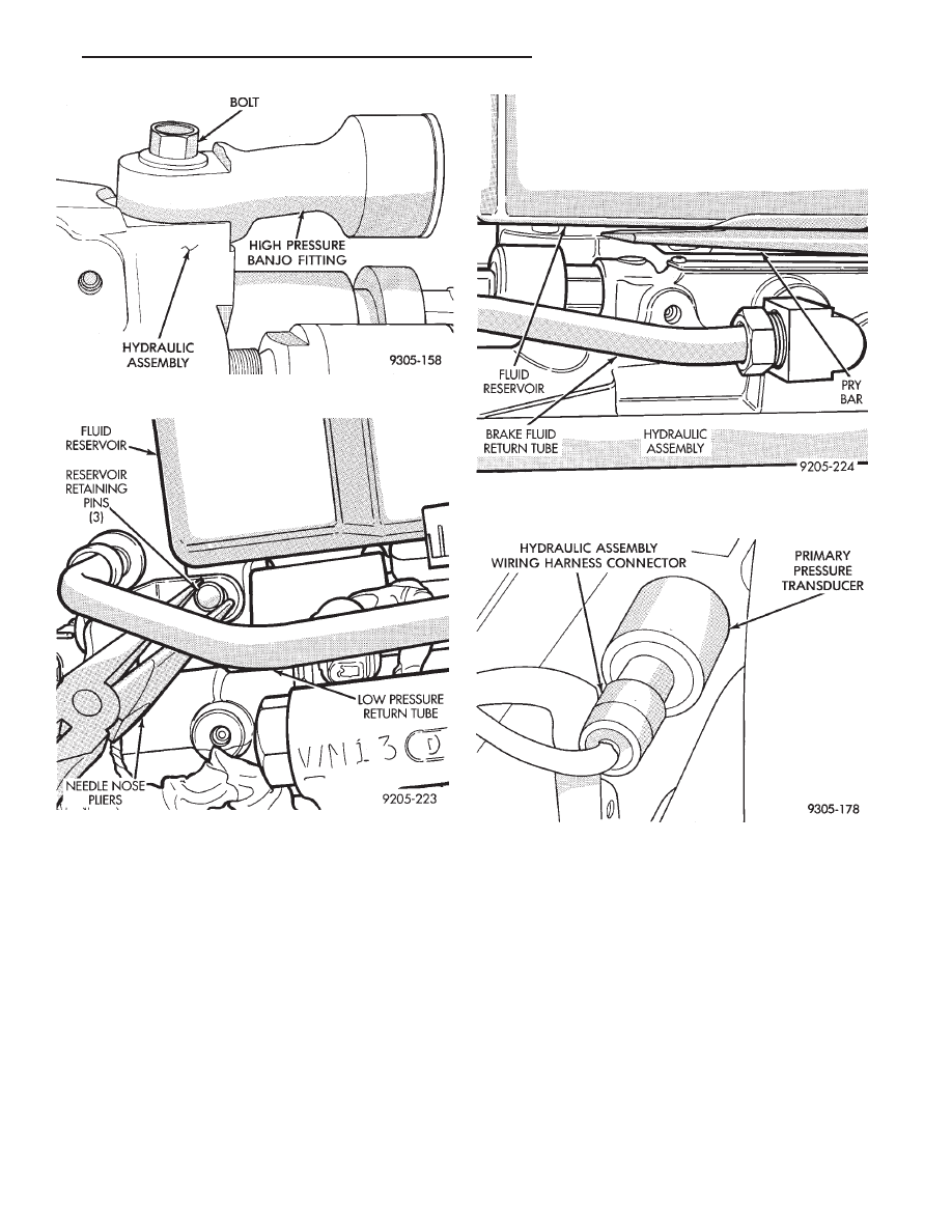
(9) Using Socket, Special Tool 6684 loosen and re-

move primary pressure transducer from hydraulic as-
sembly (Fig. 17)

INSTALL

(1) Install primary pressure transducer into hy-

draulic assembly by hand, until O-ring is fully seated
into hydraulic assembly. Then torque primary pres-
sure transducer, into hydraulic assembly, using
Socket, Special Tool 6684, to 12 N

Im (106 in. lbs.).

(2) Connect vehicle wiring harness connector, onto

primary pressure transducer (Fig. 16). Be sure latch
on vehicle wiring harness connector is fully engaged
with locking tab on primary pressure transducer.

(3) Using fingers, remove the 3 reservoir sealing

grommets from hydraulic assembly or reservoir and

discard. Sealing grommets must not be reused,
when brake fluid reservoir is installed back on
hydraulic assembly.

(4) Thoroughly lubricate new reservoir sealing

grommets, using fresh clean brake fluid, and install on
fluid reservoir outlet ports.

(5) Install brake fluid level switch into brake fluid

reservoir.

(6) Press brake fluid reservoir into hydraulic assem-

bly by hand, using a rocking motion to help seat fluid
reservoir into hydraulic assembly. Be sure that sealing
grommets are fully seated into the hydraulic assembly.
Do not attempt to pound fluid reservoir into
hydraulic assembly using a hammer.

Fig. 13 High Pressure Banjo Fitting

Fig. 14 Reservoir Retaining Pin Removal

Fig. 15 Reservoir Removal From Hydraulic Assem-

bly

Fig. 16 Wiring Harness Connection To Primary Pres-

sure Transducer

Ä

ANTI-LOCK 10 BRAKE SYSTEM

5 - 109

(7) Using needle nose pliers, install the 3 brake fluid

reservoir to hydraulic assembly retaining pins (Fig.
14). Be sure retaining pins are fully installed with
barbs extending out past reservoir on opposite
side.

(8) Install high pressure hose banjo fitting onto

hydraulic assembly and install banjo fitting attaching
bolt. Torque banjo fitting to hydraulic assembly banjo
bolt to 13 N

Im (10 ft. lbs.).

(9) Install brake fluid spray shield onto hydraulic

assembly. Install bladder accumulator into hydraulic
assembly by hand (using care not to cross thread
accumulator) until O-ring seal is fully seated into
hydraulic assembly.

(10) Using Oil Filter Band Wrench, Special Tool

C-4065 or equivalent, (Fig. 12) torque bladder accumu-
lator to 48 N

Im (35 ft. lbs.).

(11) Fill hydraulic assembly fluid reservoir to the top

of the screen on the filter\trainer. Use only fresh clean
brake fluid conforming to DOT 3 requirements, such as
Mopar

t or equivalent.

(12) Bleed the brake hydraulic system using proce-

dure shown in Bleeding Brake System in this section of
the service manual.

DIFFERENTIAL PRESSURE SWITCH

REMOVE

WARNING: FAILURE TO FULLY DE-PRESSURIZE THE
HYDRAULIC BLADDER ACCUMULATOR PRIOR TO
REMOVING

DIFFERENTIAL

PRESSURE

SWITCH.

WILL RESULT IN PERSONAL INJURY AND/OR DAM-
AGE TO PAINTED SURFACES OF THE VEHICLE.

To remove the differential pressure switch (Fig. 18),

from the hydraulic assembly, removal of the hydraulic
assembly from the vehicle is not required.

(1) De-pressurize hydraulic bladder accumulator on

hydraulic assembly by pumping the brake pedal a
minimum of 40 times. Refer to the procedure as de-
scribed in De-Pressurizing Hydraulic Accumulator
listed earlier in this section.

(2) Disconnect the hydraulic assembly wiring har-

ness connector from the primary pressure transducer
(Fig. 19).

(3) Disconnect differential pressure switch wiring

harness connector from hydraulic assembly wiring
harness (Fig. 19). Do not attempt to remove wiring
harness from differential pressure switch.

(4) Raise vehicle on a frame contact type hoist. See

Hoisting in the Lubrication And Maintenance section
of this manual, for the required lifting procedure to be
used for this vehicle.

(5) Using a long extension and Socket, Special Tool

6684 loosen and remove differential pressure switch
from bottom of hydraulic assembly (Fig. 20)

Fig. 18 Differential Pressure Switch Location

Fig. 19 Primary Pressure Transducer And Differen-

tial Pressure Switch Wiring Harness Connectors

Fig. 17 Primary Pressure Transducer Removal And

Replacement

5 - 110

ANTI-LOCK 10 BRAKE SYSTEM

Ä

INSTALL

(1) Install differential pressure switch into hydrau-

lic assembly by hand, until fully threaded into hy-
draulic assembly. Then torque differential pressure
switch, into hydraulic assembly, using Socket, Spe-
cial Tool 6684, to 1.5 N

Im (13 in. lbs.).

(2) Lower vehicle
(3) Connect differential pressure switch wiring

harness connector into hydraulic assembly wiring
harness (Fig. 19).

(4) Connect the hydraulic assembly wiring harness

connector into the primary pressure transducer (Fig.
19).

(5) Turn the ignition switch to the on position and

let the system pressurize. Check for any signs of
leakage at the differential pressure switch.

(6) Fully de-pressurize the hydraulic assembly a

second time to purge any air out that may have en-
tered hydraulic assembly when the differential pres-
sure switch was removed. Turn the ignition switch to
the on position and let the system pressurize again.

(7) Fill hydraulic assembly fluid reservoir to the

top of the screen on the filter\trainer. Use only fresh
clean brake fluid conforming to DOT 3 requirements,
such as Mopar

t or equivalent.

(8) Road test vehicle to insure that the brake sys-

tem is performing correctly.

BOOST PRESSURE TRANSDUCER

REMOVE

WARNING: FAILURE TO FULLY DE-PRESSURIZE
THE HYDRAULIC BLADDER ACCUMULATOR PRIOR
TO REMOVING BOOST PRESSURE TRANSDUCER.
MAY RESULT IN PERSONAL INJURY AND/OR DAM-
AGE TO PAINTED SURFACES OF THE VEHICLE.

To remove the boost pressure transducer (Fig. 21),

from the hydraulic assembly, removal of the hydrau-
lic assembly from the vehicle is not required.

(1) De-pressurize hydraulic bladder accumulator on

hydraulic assembly by pumping the brake pedal a
minimum of 40 times. Refer to the procedure as de-
scribed in De-Pressurizing Hydraulic Accumulator
listed earlier in this section.

(2) Raise vehicle on a frame contact type hoist. See

Hoisting in the Lubrication And Maintenance section
of this manual, for the required lifting procedure to
be used for this vehicle.

(3) Disconnect hydraulic assembly wiring harness

connectors from the dual function pressure switch
and boost pressure transducer (Fig. 21).

(4) Using a long extension and Socket, Special Tool

6607, remove dual function pressure switch from bot-
tom of hydraulic assembly (Fig. 22)

(5) Remove boost pressure transducer from hydrau-

lic assembly, from under vehicle using a long exten-
sion and Socket, Special Tool 6684 (Fig. 23).

Fig. 20 Differential Pressure Switch Removal And

Replacement

Fig. 21 Boost Pressure Transducer Location

Fig. 22 Remove And Install Dual Function Pressure

Switch

Ä

ANTI-LOCK 10 BRAKE SYSTEM

5 - 111

INSTALL

(1) Install boost pressure transducer (Fig. 23) into

hydraulic assembly by hand, until O-ring is fully
seated into hydraulic assembly. Then torque boost

pressure transducer, into hydraulic assembly, using
Socket, Special Tool 6684, to 12 N

Im (106 in. lbs.).

(2) Install Dual Function Pressure Switch (Fig. 22)

into hydraulic assembly by hand, until O-ring is
fully seated into hydraulic assembly. Then torque
dual function pressure switch, into hydraulic assem-
bly, using Socket, Special Tool 6607, to 12 N

Im (106

in. lbs.).

(3) Connect hydraulic assembly wiring harness

connectors, onto the dual function pressure switch
and boost pressure transducer (Fig. 21).

(4) Turn the ignition switch to the on position and

let the system pressurize. Check for any signs of
leakage at the differential pressure switch.

(5) Fully de-pressurize the hydraulic assembly a

second time to purge any air out that may have en-
tered hydraulic assembly when the differential pres-
sure switch was removed. Turn the ignition switch to
the on position and let the system pressurize again.

(6) Fill hydraulic assembly fluid reservoir to the

top of the screen on the filter\trainer. Use only fresh
clean brake fluid conforming to DOT 3 requirements,
such as Mopar

t or equivalent.

(7) Road test vehicle to insure that the brake sys-

tem is performing correctly.

Fig. 23 Remove And Install Boost Pressure

Transducer

5 - 112

ANTI-LOCK 10 BRAKE SYSTEM

Ä


Content   ..  237  238  239  240   ..