Chrysler Le Baron, Dodge Dynasty, Plymouth Acclaim. Manual - part 233


  Index      Chrysler     Chrysler Le Baron, Dodge Dynasty, Plymouth Acclaim - service repair manual 1993 year


Search            


Content   ..  231  232  233  234   ..


Chrysler Le Baron, Dodge Dynasty, Plymouth Acclaim. Manual - part 233


ABS HYDRAULIC CIRCUITS AND VALVE
OPERATION

Through the following operation descriptions and

diagrams. The function of the various hydraulic con-
trol valves in the ABS system will be described. The
fluid control valves mentioned below, control the flow
of pressurized brake fluid to the wheel brakes during
the different modes of Anti-Lock Braking.

NORMAL BRAKING

ISOLATION VALVES

Open to primary and secondary master cylinder

brake fluid supply (Fig. 11)

DECAY AND BUILD VALVES

Closed, not allowing for the build-up or release of

brake fluid supply (Fig. 11).

The brake pedal is applied. The travel of the brake

pedal closes primary, secondary and booster servo
circuits from fluid supply at the fluid reservoir.
Brake fluid from the primary and secondary circuits
flows through the open isolation valves and applies
the wheel brakes. Fluid from the booster servo cir-

cuit does not flow to the wheel brakes. The fluid flow
is blocked by the closed build valves and check
valves.

POWER ASSIST

The boost control valve shuttles between its three

positions to provide power assisted braking (Fig. 11).

ABS BRAKING-BUILD PRESSURE

ISOLATION VALVES

Closed, isolating wheel brakes from master cylin-

der primary and secondary fluid supplies and open to
booster servo circuit pressure through open build
valves (Fig. 12)

DECAY VALVES

Closed, not allowing the escape of pressurized fluid

supply from the hydraulic system (Fig. 12).

BUILD VALVES

Open, allowing booster servo circuit pressure to

flow to the wheel brakes through the isolation valves
(Fig. 12).

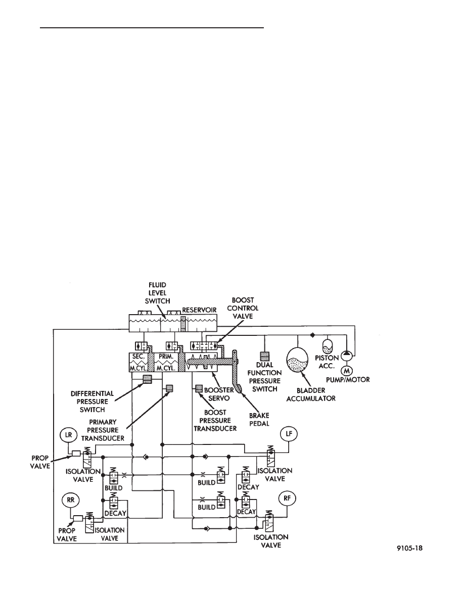
Fig. 11 Normal Braking - Hydraulic Control

Ä

ANTI-LOCK 10 BRAKE SYSTEM

5 - 85

POWER ASSIST

The boost control valve shuttles between its three

positions to provide power assisted braking (Fig. 12).

ABS BRAKING-HOLD PRESSURE

For explanation purposes we will assume all speed

sensors are sending the same wheel speed informa-
tion, requiring the same modulation at the same
rate.

ISOLATION VALVES

Closed, isolating the wheel brakes from the master

cylinder primary and secondary fluid supplies. Build
and decay valves are closed preventing any fluid
from reaching the open isolation valves (Fig. 13).

DECAY AND BUILD VALVES

Closed, not allowing fluid supply to reach the open

isolation valves (Fig. 13).

ABS BRAKING-DECAY PRESSURE

ISOLATION VALVES

Closed, isolating the wheel brakes from the master

cylinder primary and secondary fluid supplies (Fig.
14)

DECAY VALVES

Open, allowing release of fluid pressure through

decay valve to the fluid reservoir (Fig. 14)

BUILD VALVE

Closed, blocking booster servo circuit fluid to wheel

brakes (Fig. 14).

Fig. 12 Build Pressure - Hydraulic Control

5 - 86

ANTI-LOCK 10 BRAKE SYSTEM

Ä

ABS BRAKING SYSTEM DIAGNOSIS

WARNING: SOME OPERATIONS IN THIS SECTION
REQUIRE THAT HYDRAULIC TUBES, HOSES AND
FITTINGS BE DISCONNECTED FOR INSPECTION
OR TESTING PURPOSES. THIS BRAKE SYSTEM
USES A HYDRAULIC ACCUMULATOR THAT, WHEN
FULLY CHARGED, CONTAINS BRAKE FLUID AT
HIGH PRESSURE. BEFORE DISCONNECTING ANY
HYDRAULIC TUBE, HOSE OR FITTING. BE SURE
THAT THE ACCUMULATOR IS FULLY DE-PRES-
SURIZED AS DESCRIBED IN THIS SECTION. FAIL-
URE

TO

DE-PRESSURIZE

THE

ACCUMULATOR

MAY RESULT IN PERSONAL INJURY AND/OR DAM-
AGE TO PAINTED SURFACES.

CAUTION: Certain components of the Anti-Lock
Brake System (ABS) are not intended to be serviced
individually. Attempting to remove or disconnect
certain system components, may result in personal
injury and/or improper system operation. Only
those components with approved removal, service
and installation procedures described in this man-
ual should be serviced.

GENERAL INFORMATION

This section contains information necessary to di-

agnosis mechanical conditions that can affect opera-
tion of the Bendix Anti-Lock 10 Brake System.
Specifically, this section should be used to help diag-
nose mechanical conditions that result in any of the
following:

CAUTION: Review this entire section before per-
forming any mechanical work on a vehicle equipped
with the Bendix Anti-Lock 10 brake system. For in-
formation on precautions pertaining to potential
component damage, vehicle damage and personal
injury.

(1) Anti-Lock warning lamp illuminated
(2) BRAKE warning lamp on
(3) Lack of Power Assist or Excessive Pedal Travel
(4) Brakes Lock on Hard Application
Diagnosis of conditions that are obviously mechan-

ical in nature. Such as brake noise, brake pulsation,
or vehicle vibration during normal braking. Should
be directed to Group 5 Brakes in the service manual.
This also pertains to problems involving the parking
brake system.

Fig. 13 Hold Pressure - Hydraulic Control

Ä

ANTI-LOCK 10 BRAKE SYSTEM

5 - 87

In order to effectively diagnose an Anti-Lock Brake

System (ABS) condition. It is important to read Sec-
tion 1 of this manual, Anti-Lock Brake System De-
scription. This section will give you information on
the function of the ABS components. Then follow the
diagnostic procedures outlined in this section.

Many conditions that generate customer com-

plaints of the ABS system may be normal operating
conditions. These conditions though are judged to be
a problem due to unfamiliarity with the ABS system.
These conditions can be recognized without perform-
ing extensive diagnostic work, given adequate under-
standing of operating principles and performance
characteristics of the ABS system. See Section 1 of
this manual to familiarize yourself with the operat-
ing principles of the ABS system.

DEFINITIONS

Several abbreviations are used in this manual.

They are presented here for reference.
• CAB—Controller Anti-Lock Brake

• ABS—Anti-Lock Brake System

• PSI—Pounds per Square Inch (pressure)

• WSS—Wheel Speed Sensor

ABS CONTROLLER ANTI-LOCK BRAKE (CAB) SER-
VICE PRECAUTIONS

The ABS system uses an electronic control module,

the (CAB). This module is designed to withstand nor-
mal current draws associated with vehicle operation.
However care must be taken to avoid overloading the
(CAB) circuits. In testing for open or short circuits, do
not ground or apply voltage to any of the circuits unless
instructed to do so by the appropriate diagnostic pro-
cedure. These circuits should only be tested using a
high impedance multi-meter, special tools or the DRB
II tester as described in this section. Power should
never be removed or applied to any control module with
the ignition in the ON position. Before removing or
connecting battery cables, fuses, or connectors, always
turn the ignition to the OFF position.

ABS SYSTEM GENERAL SERVICE PRECAUTIONS

TEST DRIVING ABS COMPLAINT VEHICLES

Most ABS complaints will require a test drive as a

part of the diagnostic procedure. The purpose of the
test drive is to duplicate the condition.

Before test driving a brake complaint vehicle,

especially if the Red Brake Warning Lamp is on.
Test the brake function at low speed to be sure
that the car will stop normally. Remember that
conditions that result in illumination of the Red

Fig. 14 Decay Pressure - Hydraulic Control

5 - 88

ANTI-LOCK 10 BRAKE SYSTEM

Ä


Content   ..  231  232  233  234   ..