Index Chrysler Chrysler Le Baron, Dodge Dynasty, Plymouth Acclaim - service repair manual 1993 year
Search
Content .. 230 231 232 233 ..
Chrysler Le Baron, Dodge Dynasty, Plymouth Acclaim. Manual - part 232
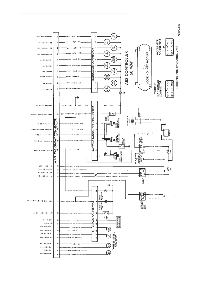
ABS
SYSTEM
WIRING
SCHEMATIC
Ä
ANTI-LOCK 10 BRAKE SYSTEM
5 - 81