Chrysler Le Baron, Dodge Dynasty, Plymouth Acclaim. Manual - part 223


  Index      Chrysler     Chrysler Le Baron, Dodge Dynasty, Plymouth Acclaim - service repair manual 1993 year


Search            


Content   ..  221  222  223  224   ..


Chrysler Le Baron, Dodge Dynasty, Plymouth Acclaim. Manual - part 223


REAR DISC BRAKES

INDEX

page

page

Assembling Rear Disc Brake Caliper

. . . . . . . . . . 49

Brake Shoe Removal

. . . . . . . . . . . . . . . . . . . . . 46

Cleaning and Inspection

. . . . . . . . . . . . . . . . . . . 49

Disassembling Rear Caliper Assembly

. . . . . . . . . 48

General Information

. . . . . . . . . . . . . . . . . . . . . . . 45

Lining Wear

. . . . . . . . . . . . . . . . . . . . . . . . . . . . . 45

Service Precautions

. . . . . . . . . . . . . . . . . . . . . . . 46

GENERAL INFORMATION

The rear disc brakes are similar to front disc

brakes, however, there are several distinctive fea-
tures that require different service procedures. This
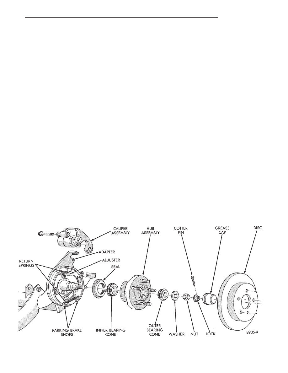
single piston, floating caliper rear disc brake assem-
bly includes a hub assembly, adapter, braking disc
(rotor), caliper, shoes and linings. The parking brake
system on all vehicles equipped with rear disc
brakes. Consists of a small duo-servo drum brake
mounted to the caliper adapter. The drum brake
shoes expand out against a braking surface (hat sec-
tion) on the inside area of the braking disk (rotor).

The AC and AY body vehicles are equipped with a

caliper assembly that has a 36 mm (1.42 inch) piston,
and utilizes a 14 inch solid braking disc (rotor).

The AA body vehicle are equipped with a caliper

assembly that uses a 34 mm (1.34 inch) piston. The
AA body uses the same 14 inch solid braking disc
(rotor) as on the AC and AY applications. Also avail-
able on the AA body is a caliper assembly with a 36
mm (1.42 inch) piston, with a 15 inch vented braking
disc (rotor).

The AG AJ and AP body vehicles are also equipped

with different size caliper pistons depending on the

size and type of braking disk used on the vehicle.
The 14

9 solid braking disk (rotor) applications use a

34 mm (1.34 inch) piston, and the 15

9 vented braking

disk (rotor) applications use a 36 mm (1.42 inch) pis-
ton.

The caliper assembly on all applications float on

rubber bushings using internal metal sleeves which
are attached to the adapter using threaded guide pin
bolts.

The adapter is mounted to the rear axle of the ve-

hicle and is used to mount the brake shoes and actu-
ating cables for the parking brake system. The
adapter also mounts the rear caliper assembly to the
vehicle. The adapter has two machined abutments
which are used to position and align the caliper and
brake shoes for movement for and aft (Fig. 1)

LINING WEAR

To check the amount of lining wear, remove the

wheel and tire assemblies. If a visual inspection does
not adequately determine the condition of the lining,

Fig. 1 Rear Disc Brake Assembly

Ä

BRAKES

5 - 45

removal will be necessary. Remove the shoe and lin-
ing assemblies (see Brake Shoe Removal).

Combined shoe and lining thickness should be

measured at the thinnest part of the assembly.

When a shoe and lining assembly is worn to a

thickness of approximately 7.0 mm (9/32 inch) it
should be replaced.

Replace both shoe assemblies (inboard and out-

board) on both wheels whenever shoe assemblies on
either side are replaced.

If a shoe assembly does not require replacement.

Reinstall it, making sure each shoe assembly is re-
turned to its original position on the wheel of the ve-
hicle from which it was removed. (See Brake Shoe
Installation).

SERVICE PRECAUTIONS

WARNING: DUST AND DIRT ON BRAKE PARTS
GENERATED DURING THE NORMAL USE AND
WEAR OF MOTOR VEHICLE BRAKE SYSTEMS CAN
CONTAIN ASBESTOS FIBERS. BREATHING EXCES-
SIVE CONCENTRATIONS OF ASBESTOS FIBERS
CAN CAUSE SERIOUS BODILY HARM, SUCH AS
ASBESTOSIS

AND

CANCER.

EXTREME

CARE

SHOULD

BE

EXERCISED

WHILE

SERVICING

BRAKE ASSEMBLIES OR COMPONENTS.

DO NOT CLEAN BRAKE ASSEMBLIES OR COM-

PONENTS WITH COMPRESSED AIR OR BY DRY
BRUSHING; USE A VACUUM CLEANER SPECIFI-
CALLY RECOMMENDED FOR USE WITH ASBES-
TOS FIBERS. IF A SUITABLE VACUUM CLEANER IS
NOT AVAILABLE, CLEANING SHOULD BE DONE
WET USING A WATER DAMPENED CLOTH.

DO NOT CREATE DUST BY SANDING, GRINDIN-

G,AND/OR SHAVING BRAKE LININGS OR PADS
UNLESS SUCH OPERATION IS DONE WHILE USING
PROPERLY EXHAUST VENTILATED EQUIPMENT.

DISPOSE OF ALL DUST AND DIRT SUSPECTED

TO CONTAIN ANY ASBESTOS FIBERS IN SEALED
BAGS OR CONTAINERS TO MINIMIZE DUST EXPO-
SURE TO YOURSELF AND OTHERS.

FOLLOW ALL RECOMMENDED PRACTICES PRE-

SCRIBED BY THE OCCUPATIONAL SAFETY AND
HEALTH ADMINISTRATION AND THE ENVIRON-
MENTAL PROTECTION AGENCY. FOR THE HAN-
DLING, PROCESSING, AND DISPOSITION OF DUST
OR DIRT WHICH MAY CONTAIN ASBESTOS FI-
BERS.

IT IS RECOMMENDED NOT TO BREATH ANY

TYPE OF BRAKE LINING MATERIAL DUST EVEN
ASBESTOS FREE, DUE TO THE FIBROUS NATURE
OF THE MATERIALS BEING USED.

Grease or any other foreign material must be kept

off the caliper assembly, surfaces of the braking disc
and external surfaces of the hub, during service pro-
cedures.

Handling the braking disc and caliper should be done

in such a way as to avoid deformation of the disc and
scratching or nicking the brake linings (pads).

During removal and installation of a wheel and tire

assembly, use care not to strike the caliper.

Before vehicle is moved after any brake service

work, be sure to obtain a firm brake pedal.

BRAKE SHOE REMOVAL

(1) Raise vehicle on jackstands or centered on a

hoist.

(2) Remove rear wheel and tire assemblies.
(3) Remove caliper attaching bolts (Fig. 2).

(4) Lift caliper away from adapter rails (Fig. 3).
(5) Remove outboard shoe. By prying the shoe re-

taining clip over the raised area on the caliper. Then
slide the shoe down and off the caliper (Fig. 4).

(6) Pull inboard shoe away from piston, until the

retaining clip is free from the cavity in the piston. (Fig.
5).

CLEANING AND INSPECTION

Check for piston seal leaks (brake fluid in and

around boot area and inboard lining) and for any
ruptures of piston dust boot. If the boot is damaged, or
fluid leak is visible, disassemble caliper assembly and
install a new seal and boot (and piston if scored). Refer
to procedure titled Disc Brake Caliper Disassembly.

BRAKE SHOE INSTALLATION

(1) Retract piston.
If the originally removed brake shoe assem-

blies are to be replaced back on vehicle. Be sure

Fig. 2 Removing Caliper Attaching Bolts

5 - 46

BRAKES

Ä

each brake shoe assembly is returned to its origi-
nal position on the wheel of the vehicle from
which it was removed.

(2) Install inboard brake shoe by inserting shoe

retaining clip into piston cavity. Be sure brake shoe is
seated squarely on the face of the piston. (Fig. 5).

(3) Install outboard shoe by sliding retaining clip

over caliper fingers. Be sure the brake shoe is installed
on the caliper, so the retaining clip is past the raised
area on the caliper fingers (Fig. 6).

(4) Install lower end of caliper on to adapter. Make

sure the lower tabs on the brake shoes and the cast-
ing projections on the caliper are under the adapter
rail (Fig. 7).

(5) Rotate caliper down over rotor.
(6) Install caliper attaching bolts and tighten to 22

N

Im (193 in. lbs.) torque (Fig. 8).

(7) Install wheel and tire assembly. Tighten stud

nuts in proper sequence until all nuts are torqued to
half specification. This is important. Then repeat
sequence to full specification.

(8) Remove jackstands or lower hoist. Before mov-

ing vehicle be sure it has a firm pedal.

Fig. 5 Remove and Install Inboard Brake Shoe

Fig. 6 Installing Outboard Shoe

Fig. 3 Removing Caliper

Fig. 4 Removing Outboard Shoe

Ä

BRAKES

5 - 47

DISASSEMBLING REAR CALIPER ASSEMBLY

CLEANING AND INSPECTION

Check for piston fluid seal leaks (brake fluid in and

around boot area and inboard lining) and for any
ruptures of piston dust boot. If boot is damaged, or
fluid leak is visible, disassemble caliper assembly
and install a new seal and boot,(and piston if scored).
Refer to procedures titled Disc Brake Caliper Disas-
sembly.

Check the caliper dust boot and caliper pin bush-

ings to determine if they are in good condition. Re-

place if they are damaged, dry, or found to be brittle.
Refer to Cleaning And Inspection Of Brake Caliper.

(1) Remove caliper from braking disc (See Brake

Shoe Removal). Hang assembly on a wire hook away
from braking disc, so hydraulic fluid cannot get on
braking disc (See Fig. 4 in Brake Shoe Removal). Place
a small piece of wood between the piston and caliper
fingers.

(2) Carefully depress brake pedal to hydraulically

push piston out of bore. (Brake pedal will fall away
when piston has passed bore opening.) Then prop up
the brake pedal to any position below the first inch of
pedal travel, this will prevent loss of brake fluid from
the master cylinder.

(3) If both front caliper pistons are to be removed,

disconnect flexible brake line at frame bracket after
removing piston. Plug brake tube and remove piston
from opposite caliper. Using the same process as above
for the first piston removal.

WARNING: UNDER NO CONDITION SHOULD AIR
PRESSURE BE USED TO REMOVE PISTON FROM
CALIPER BORE. PERSONAL INJURY COULD RE-
SULT FROM SUCH A PRACTICE.

(4) Disconnect brake flexible hose from the caliper.

To disassemble, mount caliper assembly in a vise
equipped with protective jaws.

CAUTION: Excessive vise pressure will cause bore
distortion and binding of piston.

Support rear caliper assembly in a vise. Then remove

caliper to piston dust boot and discard (Fig. 1).

Using a plastic trim stick, work piston seal out of its

groove in caliper piston bore (Fig. 2). Discard old seal.
Do not use a screwdriver or other metal

Fig. 7 Installing Caliper

Fig. 8 Installing Attaching Bolts

Fig. 1 Removing Piston Dust Boot

5 - 48

BRAKES

Ä


Content   ..  221  222  223  224   ..