Chrysler Le Baron, Dodge Dynasty, Plymouth Acclaim. Manual - part 221


  Index      Chrysler     Chrysler Le Baron, Dodge Dynasty, Plymouth Acclaim - service repair manual 1993 year


Search            


Content   ..  219  220  221  222   ..


Chrysler Le Baron, Dodge Dynasty, Plymouth Acclaim. Manual - part 221


material, (Fig. 7). Be sure inboard brake shoe assem-
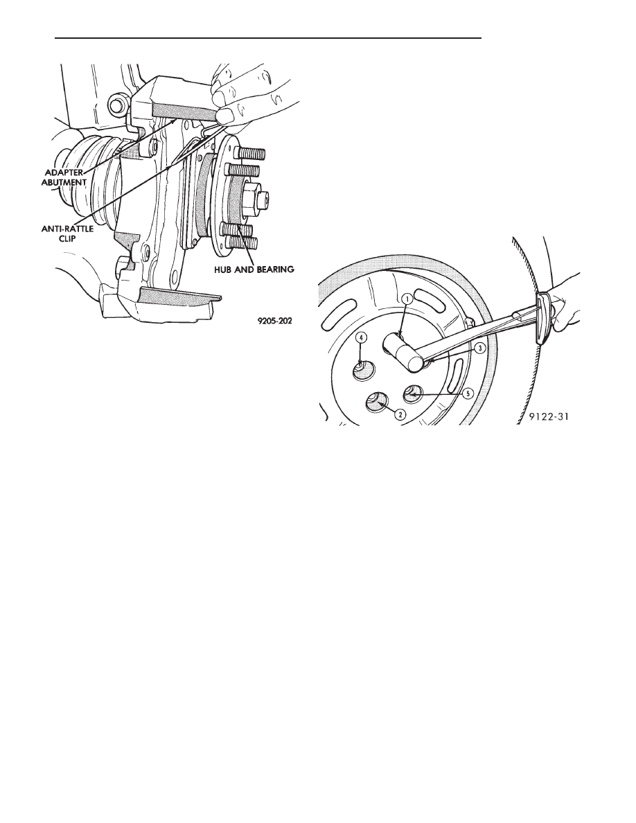
bly is correctly positioned against anti-rattle clip
(Fig. 6).

(4) Reinstall the Braking Disk on the hub, by in-

stalling it over the wheel studs until it is seated
against the face of the hub (Fig. 6).

(5) Slide the new outboard brake shoe assembly on

the adapter abutment, (Fig. 5).

(6) Carefully lower caliper over the braking disk and

brake shoe assemblies (Fig. 3). Make sure that the
caliper guide pin bolt, bushings and sleeves are clear of
the adapter.

(7) Install the caliper guide pin bolts and tighten to

34 to 37 N

Im (25 to 35 ft. lbs.). Extreme caution

should be taken not to cross the threads of the
caliper guide pin bolts.

(8) Install the wheel and tire assembly. Tighten the

wheel mounting stud nuts in proper sequence (Fig. 9)
until all nuts are torqued to half specification. This is
important. Then repeat the tightening sequence to the
full specified torque of 129 N

Im (95 ft. lbs.).

(9) Remove jackstands or lower hoist. Before mov-

ing vehicle, pump the brake pedal several times
to insure the vehicle has a firm brake pedal to
adequately stop vehicle.
.

(10) Road test the vehicle and make several stops to

wear off any foreign material on the brake linings and
to seat the brake shoe linings.

Fig. 8 Remove Or Replace Anti-Rattle Clip

Fig. 9 Tightening Wheel Nuts

Ä

BRAKES

5 - 37

KELSEY HAYES DOUBLE PIN NON-FAMILY CALIPER

INDEX

page

page

Assembling Disc Brake Caliper

. . . . . . . . . . . . . . 42

Cleaning and Inspection of Brake Caliper

. . . . . . 41

Disc Brake Caliper Disassembly

. . . . . . . . . . . . . 40

Service Procedures

. . . . . . . . . . . . . . . . . . . . . . . 38

SERVICE PROCEDURES

BRAKE SHOES REMOVE

(1) Raise the vehicle on jackstands or centered on

a hoist.

(2) Remove the front wheel and tire assemblies

from the vehicle.

(3) Remove the brake caliper assembly to steering

knuckle attaching guide pin bolts (Fig. 1)

(4) Pull lower end of brake caliper out from the

machined abutment on the steering knuckle (Fig. 2).
Then roll caliper out and away from braking disc
(Fig. 2). The brake shoe assemblies will remain with
the brake caliper.

(5) When the caliper is removed from the vehicle

to service the brake shoes. SUPPORT CALIPER
FIRMLY TO PREVENT WEIGHT OF CALIPER
FROM DAMAGING THE FLEXIBLE HOSE. 
(See
Fig. 3).

(6) Remove the outboard brake shoe by prying be-

tween the top of the outboard shoe and the top of the
caliper assembly as shown in (Fig. 4).

(7) Remove the inboard brake shoe from the cali-

per, by pulling the inboard shoe assembly away from
the piston (Fig. 5).

Fig. 1 Non-Family Disc Brake Assembly

Fig. 2 Removing Caliper and Brake Shoes as an

Assembly

5 - 38

BRAKES

Ä

CLEANING AND INSPECTION

Check for piston seal leaks (brake fluid in and

around boot area and inboard lining) and for any
ruptures of the piston dust boot. If boot is damaged,
or fluid leak is visible, disassemble caliper assembly
and install a new seal and boot,(and piston if scored).
Refer to procedures titled Disc Brake Caliper Disas-
sembly.

Check the caliper dust boot and caliper pin bush-

ings to determine if they are in good condition. Re-
place if they are damaged, dry, or found to be brittle.
Refer to Cleaning And Inspection Of Brake Caliper.

BRAKE SHOES INSTALL

(1) Thoroughly clean and lubricate both adapter

ways on the steering knuckle, with a liberal amount
of Mopar Multi-purpose Lubricant, or equivalent.

(2) The inboard brake shoes are common. The out-

board brake shoes are marked with an (LH) or (RH)
to denote which side of the vehicle to be installed on
(Fig. 6).

(3) Remove protective paper from the noise sup-

pression gasket and position the properly marked
outboard brake shoe assembly onto the caliper (Fig.
7).

(4) Install new inboard brake shoe assembly in cal-

Fig. 3 Storing Caliper

Fig. 4 Prying Outboard Shoe Assembly Away from

Caliper

Fig. 5 Removing or Installing Inboard Shoe

Assembly

Fig. 6 Brake Shoe Identification

Ä

BRAKES

5 - 39

iper, by installing retaining clip into the bore of the
piston (Fig. 5).

CAUTION: Use care when installing the caliper as-
sembly onto the steering knuckle, so the seal on the
sealed for life bushings does not get damaged.

(5) Carefully lower caliper over braking disc and

guide holddown spring under machined abutment on
knuckle assembly (Fig. 8).

(6) Install caliper guide pin bolts and tighten to

24-34 N

Im (18-25 ft. lbs.) torque. When installing

guide pin bolts, use extreme caution not to cross
thread the guide pin bolts.

(7) Install wheel and tire assembly. Tighten stud

nuts in proper sequence until all nuts are torqued to
half specification. This is important. Then repeat
sequence to full specification.

(8) Remove jackstands or lower hoist. Before mov-

ing vehicle be sure it has a firm pedal, pump
pedal several times.

(9) Road test vehicle and make several stops to

wear off any foreign material on the brakes and
to seat the linings.

DISC BRAKE CALIPER DISASSEMBLY

CLEANING AND INSPECTION

Check for piston fluid seal leaks (brake fluid in and

around boot area and inboard lining) and for any
ruptures of piston dust boot. If boot is damaged, or fluid
leak is visible, disassemble caliper assembly and in-
stall a new seal and boot,(and piston if scored). Refer to
procedures titled Disc Brake Caliper Disassembly.

Check the caliper dust boot and caliper pin bushings

to determine if they are in good condition. Replace if
they are damaged, dry, or found to be brittle. Refer to
Cleaning And Inspection Of Brake Caliper.

(1) Remove caliper from braking disc (See Brake

Shoe Removal). Hang assembly on a wire hook away
from braking disc, so hydraulic fluid cannot get on
braking disc (See Fig. 3 in Brake Shoe Removal). Place
a small piece of wood between the piston and caliper
fingers.

(2) Carefully depress brake pedal to hydraulically

push piston out of bore. (Brake pedal will fall away
when piston has passed bore opening.) Then prop up
the brake pedal to any position below the first inch of
pedal travel, this will prevent loss of brake fluid from
the master cylinder.

(3) If both front caliper pistons are to be removed,

disconnect flexible brake line at frame bracket after
removing piston. Plug brake tube and remove piston
from opposite caliper. Using the same process as above
for the first piston removal.

WARNING: UNDER NO CONDITION SHOULD AIR
PRESSURE BE USED TO REMOVE PISTON FROM
CALIPER BORE. PERSONAL INJURY COULD RE-
SULT FROM SUCH A PRACTICE.

(4) Disconnect brake flexible hose from the caliper.

To disassemble, mount caliper assembly in a vise
equipped with protective jaws.

CAUTION: Excessive vise pressure will cause bore
distortion and binding of piston.

Fig. 7 Installing Outboard Shoe Assembly onto Cali-

per

Fig. 8 Guiding Holddown Spring Under Machined

Abutment

5 - 40

BRAKES

Ä


Content   ..  219  220  221  222   ..