Chrysler Le Baron, Dodge Dynasty, Plymouth Acclaim. Manual - part 218


  Index      Chrysler     Chrysler Le Baron, Dodge Dynasty, Plymouth Acclaim - service repair manual 1993 year


Search            


Content   ..  216  217  218  219   ..


Chrysler Le Baron, Dodge Dynasty, Plymouth Acclaim. Manual - part 218


BRAKE SUPPORT ASSEMBLY

REMOVAL

Back off parking brake adjusting nut to provide

slack in cable.

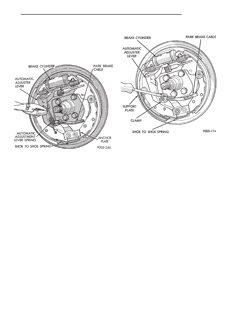
With wheel and brake drum removed, disconnect

hydraulic tube from wheel cylinder.Disconnect park-
ing brake cable and adjuster lever spring (Fig. 1).

Using a suitable tool such as an aircraft type hose

clamp, install the clamp over the retainer on the end
of the parking brake cable (Fig. 2). Compress cable
housing retainer and start housing out of support
plate (Fig. 2). Remove clamp when retainer is free
from the park brake cable mounting hole in the rear
brake support plate. Alternate method is to slide a
14 mm box wrench over housing end fitting com-
pressing the three fingers.

Remove attaching bolts and washers and separate

brake support and spindle from rear support trailing
arm.

INSTALLATION

Insert parking brake cable and housing into sup-

port plate.

Install support plate, spindle and gasket between

support plate and spindle on to rear suspension mem-
ber. Tighten support plate attaching bolts to 71 N

Im

(53 ft. lbs) torque.

Attach cable to parking brake lever.
Connect brake tube to wheel cylinder. Tighten

brake tube to wheel cylinder fitting to 17 N

Im (145

in. lbs.).

Install brake drum and wheel. Adjust and bleed

service brakes. Adjust parking brake.

Fig. 1 Removing Adjuster Lever Spring

Fig. 2 Removing Park Brake Cable From Support

Plate

Ä

BRAKES

5 - 25

HYDRAULIC SYSTEM CONTROL VALVES

INDEX

page

page

ABS Brake Proportioning Valve Operation

. . . . . . 27

General Information

. . . . . . . . . . . . . . . . . . . . . . . 26

Hydraulic System Service Procedures

. . . . . . . . . 27

Non-ABS Proportioning Unit Operation

. . . . . . . . 26

Pressure Differential Warning Light Switch

. . . . . . 26

Testing ABS Proportioning Valves

. . . . . . . . . . . . 29

GENERAL INFORMATION

Most models not equipped with an Anti-Lock brak-

ing system have a combination hydraulic system con-
trol valve in the brake hydraulic system (Fig. 1). The
valve is attached to the frame rail below the master
cylinder.

The control valve assembly combines a warning

switch with a dual proportioning valve (Fig. 2)

Proportioning valves balance front to rear braking

by controlling at a given ratio, the increase in rear
system hydraulic pressure above a preset level. Un-
der light pedal application, the valve allows full hy-
draulic pressure to the rear brakes.

There is only one valve assembly in each vehicle,

see Valve Application Chart. During any service pro-
cedures identify valve assemblies by part number as
well as split point (PSI) and slope.

PRESSURE DIFFERENTIAL WARNING LIGHT
SWITCH

The hydraulic brake system, on non-ABS vehicles,

is split diagonally. The left front and right rear
brakes are part of one system. And the right front

and left rear are part of another. Both systems are
routed through, but hydraulically separated by a Pres-
sure Differential Switch. The function of the Pressure
Differential Switch is to alert the driver of a malfunc-
tion in the brake system.

If hydraulic pressure is lost in one system, the

warning light switch will activate a red light on the
instrument panel, when the brake pedal is depressed.
At this point the brakes require service. However, since
the brake systems are split diagonally the vehicle will
retain 50% of its stopping capability in the event of a
failure in either half.

The warning light switch is the latching type. It

will automatically center itself after the repair is
made and the brake pedal is depressed.

The instrument panel bulb can be checked each time

the ignition switch is turned to the start position or the
parking brake is set.

NON-ABS PROPORTIONING UNIT OPERATION

The proportioning valve section operates by trans-

mitting full input pressure to the rear brakes up to a
certain point. This is called the split point. Beyond this
point it reduces the amount of pressure increase to the
rear brakes according to a certain ratio.

On light pedal applications equal brake pressure will

be transmitted to the front and rear brakes. On heavier
pedal

applications

the

pressure

transmitted

Fig. 1 Brake Combination Valve And Warning

Switch Location

Fig. 2 Switch and Valve Assembly

5 - 26

BRAKES

Ä

to the rear will be lower than the front brakes. This will
prevent premature rear wheel lock-up and skid. If
hydraulic pressure is lost in one half of the diagonally
split system, the operation of the proportioning valve
in the remaining half is not effected.

ABS BRAKE PROPORTIONING VALVE OPERATION

On vehicles using the ABS braking system, screw in

proportioning valves are used in place of the conven-
tional differential pressure/proportioning valve.

Each rear brake circuit has its own screw-in propor-

tioning valve which is attached to the rear brake outlet
ports of the hydraulic assembly. These valves limit
brake pressure to the rear brakes after a certain
pressure is reached. This improves front to rear brake
balance during normal braking.

Screw in proportioning valves can be identified by

the numbers stamped on the body of the valve. The
first digit represents the slope, the second digit repre-
sents the split (cut-in) point, and the arrow represents
the flow direction of the valve. Be sure that the
numbers listed on the replacement valve are the
same as on the valve that is being removed. 
See
(Fig. 3) for detail of the valve identification.

HYDRAULIC SYSTEM SERVICE PROCEDURES

BRAKE WARNING SYSTEM

CHECKING BRAKE WARNING SWITCH UNIT

The Red Brake Warning light will come on when

the parking brake is applied with the ignition key
turned ON. The same light will also illuminate
should one of the two service brake hydraulic sys-
tems fail.

CAUTION:Make sure air does not enter the hydrau-
lic system during this test procedure. See bleeding
without a pressure bleeder at the beginning of this
section for master cylinder fluid level checking pro-
cedures.

To test the service brake warning system lamp.

Raise the vehicle on a hoist and open a wheel cylin-
der bleeder while a helper depresses the brake pedal
and observes the warning light.

If the light fails to light, inspect for a burned out

bulb, disconnected socket, or a broken or discon-
nected wire at the switch. If the bulb is not burned
out and the wire continuity is uninterrupted. Check
the service brake warning switch operation with a
test lamp between the switch terminal and a known
good ground. Be sure to fill master cylinder and
bleed brake system after correction has been made, if
necessary.

PROPORTIONING VALVES

TESTING PROPORTIONING VALVE UNIT

If premature rear wheel skid occurs on hard brake

application, it could be an indication that a malfunc-
tion has occurred with the proportioning valve unit.

The proportioning valve is designed with two sep-

arate systems. One half controls the right rear
brake, and the other half controls the left rear brake.
Therefore, a road test to determine which rear brake
slides first is essential.

RIGHT REAR WHEEL SLIDES FIRST

To test the proportioning valve when the right rear

wheel slides first, leave the front brakes connected to
the valve, proceed as follows:

(1) Install one gauge and (TEE) of set C-4007-A

between the brake line from the master cylinder sec-
ondary port and the brake valve assembly.

(2) Install the second gauge of set C-4007-A to the

right rear brake outlet port (Fig. 4). Using an
adapter tube, made from a short piece of brake tube
and (2) 3/8 x 24 tube nuts. Connect the hose to the
valve. Bleed the hose and gauge.

(3) Have a helper exert pressure on the brake

pedal (holding pressure) to get a reading on the valve
inlet gauge and check the reading on the outlet

Fig. 3 ABS PROPORTIONING VALVE IDENTIFICA-

TION

Ä

BRAKES

5 - 27

PROPORTIONING VALVE APPLICATIONS

5 - 28

BRAKES

Ä


Content   ..  216  217  218  219   ..