Chrysler Le Baron, Dodge Dynasty, Plymouth Acclaim. Manual - part 217


  Index      Chrysler     Chrysler Le Baron, Dodge Dynasty, Plymouth Acclaim - service repair manual 1993 year


Search            


Content   ..  215  216  217  218   ..


Chrysler Le Baron, Dodge Dynasty, Plymouth Acclaim. Manual - part 217


If old springs have overheated or are damaged, re-

place. Overheating indications are paint discoloration
or distorted end coils. Varga brake springs are not
painted but overheating of the brake springs will be
noted by any Blueing of the springs.

BRAKE SHOE INSTALLATION

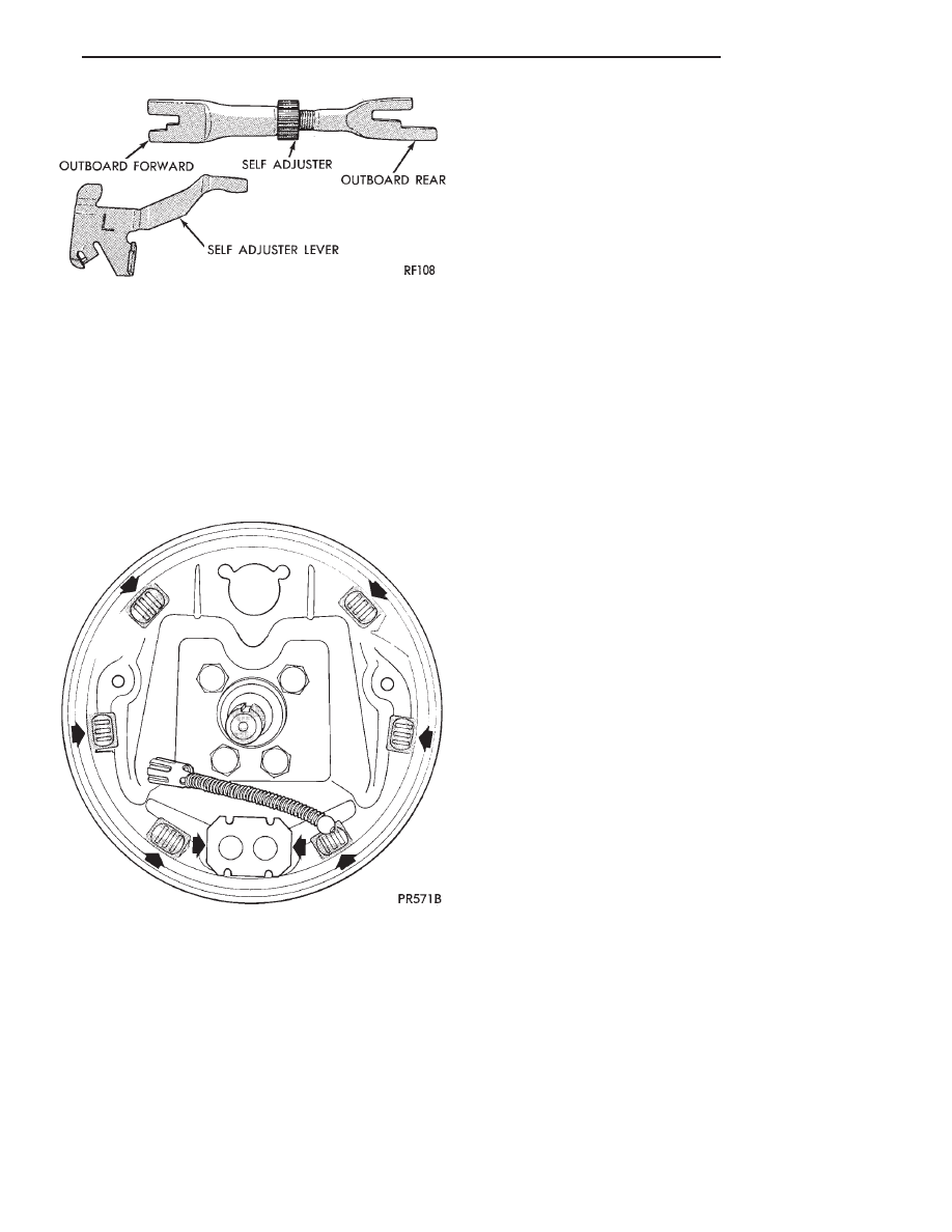
Lubricate the eight shoe contact areas on the sup-

port plate and anchor using Mopar Multi-Purpose
Lubricant or equivalent (Fig. 11).

KELSEY HAYES REASSEMBLE

Assemble the park brake lever and wave washer to

the new replacement shoe (Fig. 9).

Attach upper return spring between the two new

shoe assemblies.

Apply a small amount of Mopar Multi-Purpose Lu-

bricant or equivalent to the automatic adjuster screw
assembly. Install adjuster with the two stepped forks
facing toward the outboard side of the shoes (Fig.
10). The longer fork will be pointing to the rear.

Connect the lower shoe to shoe spring.

Expand the automatic adjuster so that the end of the

shoes will clear the wheel cylinder boots. Position the
brake shoe assemblies on support plate and install
holddown springs (Fig. 7).

Install self adjuster lever and spring.
Connect park brake cable.
Adjust brake shoes so that they will not interfere

with the drum installation.

CAUTION: Make sure the adjuster screw nut contacts
the adjuster tubular strut.

Install the drums and pump the brake pedal

several times to partially complete the shoe ad-
justment.

After adjusting the Parking brake cable (see Adjust-

ing Parking Brake), road test vehicle. The automatic
adjuster will continue the brake adjustment during the
test.

VARGA REASSEMBLE

(1) Install park brake cable in park brake lever of

trailing shoe.

(2) Attach trailing shoe, then leading shoe lower

springs to shoes and anchor plate.

(3) Position shoes on support plate and install hold-

down springs.

(4) Install automatic adjusters. Left side adjuster

has left hand threads and right side adjuster has
right-hand threads. Do not interchange sides.
Make sure adjuster is installed correctly. (Adjuster
ends must be above extruded pins in web of shoe as
shown in Fig. 3).

(5) Install upper shoe to shoe spring. Ensure that

the spring terminal ends are fully engaged in the shoe
webs.

(6) Rotate serrated adjuster nut to remove free play

from the adjuster assembly.

(7) Install the adjuster lever on the leading shoe

pivot pin. Then attach the short end of the adjuster
spring into the hole on the lever. Then install the long
end of the spring in the leading shoe hole.

(8) Connect park brake cable and adjust brake shoes

so as not to interfere with drum installation.

BRAKE DRUM REFACING

Measure drum runout and diameter. If not to speci-

fication, reface drum. (Runout should not exceed
0.1524 mm or 0.006 inch). The diameter variation (oval
shape) of the drum braking surface must not exceed
either 0.0635 mm (0.0025 inch) in 30° or 0.0889 mm
(0.0035 inch) in 360°.

All drums will show markings of maximum allowable

diameter (Fig. 12).

Fig. 10 Adjuster Screw and Lever (Typical)

Fig. 11 Shoe Contact Areas on Support Plate

Ä

BRAKES

5 - 21

Using suitable tool, remove grease seal from drum

hub. Clean, inspect and pack wheel bearings. Install
new seal (Fig. 13). See Wheel Bearings section in
this group of the service manual for detailed infor-
mation on the wheel bearings, and service proce-
dures.

Fig. 12 Maximum Drum Diameter Identification

Fig. 13 Installing Grease Seal

5 - 22

BRAKES

Ä

WHEEL CYLINDERS

INDEX

page

page

General Information

. . . . . . . . . . . . . . . . . . . . . . . 23

Installing Wheel Cylinders

. . . . . . . . . . . . . . . . . . 24

Service Procedures

. . . . . . . . . . . . . . . . . . . . . . . 23

GENERAL INFORMATION

The piston boots are of the push-on type and pre-

vent moisture from entering the wheel cylinder.

To perform service operations or inspections of the

rear wheel brake cylinders. It will be necessary to re-
move the cylinders from the support plate and disas-
semble on the bench.

CAUTION: Wheel cylinders with cup expanders
must have cup expanders after any service proce-
dures (reconditioning or replacement).

SERVICE PROCEDURES

REMOVING WHEEL CYLINDERS FROM BRAKE
SUPPORT PLATES

With brake drums removed, inspect the wheel cyl-

inder boots for evidence of a brake fluid leak. Then
block the brake pedal in the stroke position, and vi-
sually check the boots for cuts, tears, or heat cracks.
If any of these conditions exist, the wheel cylinders
should be completely cleaned, inspected and new
parts installed. (A slight amount of fluid on the boot
may not be a leak, but may be preservative fluid
used at assembly.)

(1) In case of a leak, remove brake shoes, (replace

if soaked with grease or brake fluid.)

(2) Thoroughly clean area of wheel cylinder, where

hydraulic brake line connects to wheel cylinder. Dis-
connect hydraulic brake tube from wheel cylinder
(Fig. 1).

(3) Remove the rear wheel cylinder attaching bolts

(Fig. 1). Then pull wheel cylinder assembly off the
brake support plate (Fig. 2).

(4) Clean the surface sealant off the support plate

and wheel cylinder surfaces.

DISASSEMBLING WHEEL CYLINDERS

To disassemble the wheel cylinders, (Fig. 3) pro-

ceed as follows:

(1) Pry boots away from cylinders and remove.
(2) Press IN on one piston to force out opposite pis-

ton, cup and spring (with cup expanders). Then using
a soft tool such as a dowel rod, press out the cup and
piston that remain in the wheel cylinder.

(3) Wash wheel cylinder, pistons, and spring in

clean brake fluid or alcohol; (DO NOT USE ANY
PETROLEUM BASE SOLVENTS) 
clean thor-

oughly and blow dry with compressed air. Inspect

Fig. 1 Brake Tube Disconnected

Fig. 2 Remove or Install Wheel Cylinder

Ä

BRAKES

5 - 23

cylinder bore and piston for scoring and pitting. (Do
not use a rag as lint from the rag will stick to bore
surfaces.)

Wheel cylinder bores and pistons that are scored or

pitted in any way should be replaced. Cylinder walls
that have light scratches, or show signs of corrosion,
can usually be cleaned with crocus cloth, using a cir-
cular motion. Black stains on the cylinder walls are
caused by piston cups and will not impair operation
of cylinder.

ASSEMBLING WHEEL CYLINDERS

Before assembling the pistons and new cups in the

wheel cylinders, dip them in clean brake fluid. If the
boots are deteriorated, cracked or do not fit tightly
on the pistons or the cylinder casting, install new
boots.

(1) Coat cylinder bore with clean brake fluid.
(2) Install expansion spring with cup expanders in

cylinder. Install cups in each end of cylinder with
open end of cups facing each other (Fig. 3).

(3) Install piston in each end of cylinder having

the flat face of each piston contacting the flat face of
each cup, already installed (Fig. 3).

(4) Install a boot over each end of cylinder. Be

careful not to damage boot during installation.

INSTALLING WHEEL CYLINDERS

(1) Apply Mopar

t Gasket In-A-Tube or equivalent

sealant around wheel cylinder mounting surface (Fig.
4).

(2) Install wheel cylinder onto brake support, and

tighten the wheel cylinder to brake support plate at-
taching bolts to 8 N

Im (75 in. lbs.).

(3) Attach hydraulic brake tube to wheel cylinder,

and tighten tube to wheel cylinder fitting to 17 N

Im

(145 in. lbs.).

(4) Install brake shoes on support plate.
(5) Install rear brake drum onto rear hub. Install

rear wheel and tire assembly, tighten wheel stud
nuts to 115 N

Im (85 ft. lbs.).

(6) Adjust the rear brakes, (See Adjusting Service

Brakes) in Service Adjustments section in this group
of the service manual.

(7) Bleed the entire brake system. See (Bleeding

Brake System) in Service Adjustments section in this
group of the service manual.

Fig. 3 Rear Wheel Cylinder

Fig. 4 Apply Sealant on Support Plate

5 - 24

BRAKES

Ä


Content   ..  215  216  217  218   ..