Index Chrysler Chrysler Le Baron, Dodge Dynasty, Plymouth Acclaim - service repair manual 1993 year
Search
Content .. 212 213 214 215 ..
Chrysler Le Baron, Dodge Dynasty, Plymouth Acclaim. Manual - part 214
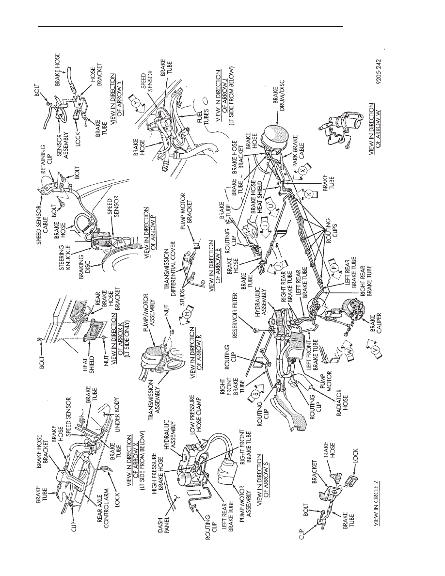
FIG.
11
BRAKE
LINE
ROUTING
WITH
ANTI-LOCK
10
BRAKES
Ä
5 - 9