Chrysler Le Baron, Dodge Dynasty, Plymouth Acclaim. Manual - part 213


  Index      Chrysler     Chrysler Le Baron, Dodge Dynasty, Plymouth Acclaim - service repair manual 1993 year


Search            


Content   ..  211  212  213  214   ..


Chrysler Le Baron, Dodge Dynasty, Plymouth Acclaim. Manual - part 213


should be taken so as not to bend adjusting lever
or distort lever spring. 
While holding adjusting
lever out of engagement with star wheel, back off star
wheel to ensure a free wheel with no brake shoe drag.

(6) Repeat above adjustment at the other rear wheel.

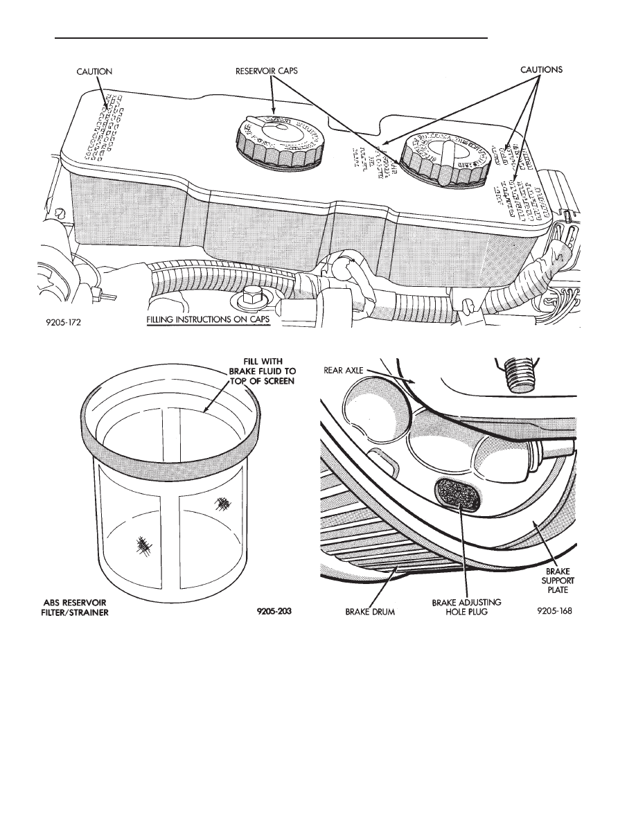
Install adjusting hole rubber plugs (Fig. 4) in rear
brake supports.

(7) Adjust parking brake after wheel brake adjust-

ment. See parking brake adjustment, under Parking
Brakes in this group of the service manual.

It is important to follow the above sequence to

avoid the possibility of the parking brake system
causing brake drag. This could occur if the park-
ing brakes are adjusted before the service
brakes.

Fig. 4 Brake Adjusting Hole Plug

Fig. 2 Master Cylinder Fluid Level (W/ABS)

Fig. 3 ABS Reservoir Fill Level On Filter/Strainer

Ä

BRAKES

5 - 5

TESTING APPLICATION ADJUSTER OPERATION

Place the vehicle on a hoist with a helper in the

driver’s seat to apply the brakes. Remove the access
plug from the rear adjustment slot in each brake
support plate (Fig. 4) to provide access to the ad-
juster star wheel. Then, to eliminate the possibility
of maximum adjustment, where the adjuster does not
operate because the closest possible adjustment has
been reached. Back the star wheel off approximately
30 notches. It will be necessary to hold the adjuster
lever away from the star wheel to permit this adjust-
ment.

Spin the wheel and brake drum in the reverse di-

rection, and with a greater than normal force apply
the brakes suddenly. This sudden application of force
will cause the secondary brake shoe to leave the an-
chor. The wrap up effect will move the secondary
shoe, and the cable will pull the adjuster lever up.
Upon application of the brake pedal, the lever should
move upward, turning the star wheel. Thus, a defi-
nite rotation of the adjuster star wheel can be ob-
served if the automatic adjuster is working properly.
If one or more adjusters do not function properly, the
respective drum must be removed for adjuster servic-
ing.

BLEEDING BRAKE SYSTEM

CAUTION: For bleeding of the Anti-Lock brake hy-
draulic system. See the Anti-Lock Brake system
service procedures in this group which refers to the
particular Anti-Lock brake system being serviced.

PRESSURE BLEEDING

Before removing the master cylinder cover, wipe it

clean to prevent dirt and other foreign matter from
dropping into the master cylinder.

CAUTION: Use bleeder tank Special Tool C-3496-B
with adapter Special Tool C-4578 to pressurize the
system for bleeding.

Follow pressure bleeder manufacturer’s instruc-

tions, for use of pressure bleeding equipment.

When bleeding the brake system. Some air may be

trapped in the brake lines or valves far upstream. As
much as ten feet from the bleeder screw (Fig. 6).
Therefore, it is essential to have a fast flow of a large
volume of brake fluid when bleeding the brakes to
ensure all the air gets out.

The following wheel sequence for bleeding the

brake hydraulic system should be used to ensure ad-
equate removal of all trapped air from the hydraulic
system.
• Right rear wheel

• Left front wheel

• Left rear wheel

• Right front wheel

To bleed the brake system. Attach a clear plastic

hose to the bleeder screw starting at the right rear
wheel and feed the hose into a clear jar containing
fresh brake fluid (Fig. 7).

Next, open the bleeder screw at least one full turn

or more to obtain an adequate flow of brake fluid
(Fig. 8).

CAUTION: Just cracking the bleeder screw often re-
stricts fluid flow, and a slow, weak fluid discharge
will NOT get all the air out.

After 4 to 8 ounces of fluid has been bled through

the brake system at this wheel. And an air-free flow
is maintained in the clear plastic hose and jar, this
will indicate a good bleed.

Repeat the procedure at all the other remaining

bleeder screws. Then check the pedal for travel. If
pedal travel is excessive or has not been improved.
Enough fluid has not passed through the system to

Fig. 5 Brake Drum Adjustment With Tool C-3784

Fig. 6 Trapped Air in Brake Line

5 - 6

BRAKES

Ä

expel all the trapped air. Be sure to monitor the fluid
level in the pressure bleeder. It must stay at the
proper level so air will not be allowed to reenter the
brake system through the master cylinder.

BLEEDING WITHOUT A PRESSURE BLEEDER

If a pressure bleeder is not available. A good brake

fluid flow can be obtained by manual bleeding of the
brake hydraulic system, following these steps.

Manual bleeding of the brakes hydraulic sys-

tem will require the aid of a helper to correctly
perform manual brake bleeding procedure.

The following wheel sequence for bleeding the

brake hydraulic system should be used to ensure ad-
equate removal of all trapped air from the hydraulic
system.

• Right rear wheel

• Left front wheel

• Left rear wheel

• Right front wheel

(1) Pump the brake pedal three or four times and

hold it down before the bleeder screw is opened.

(2) Then open the bleeder screw at least 1 full

turn. When the bleeder screw opens the brake pedal
will drop all the way to the floor.

(3) Release the brake pedal only after the bleeder

screw is closed.

(4) Repeat steps 1 through 3, four or five times, at

each bleeder screw. This should pass a sufficient
amount of fluid to expel all the trapped air from the
brake system. Be sure to monitor the fluid level in
the master cylinder, so it stays at a proper level so
air will not reenter the brake system through the
master cylinder.

Test drive vehicle to be sure brakes are operating

correctly and that pedal is solid.

TEST FOR FLUID CONTAMINATION

Indications of fluid contamination are swollen or

deteriorated rubber parts.

Swollen rubber parts indicate the presence of petro-

leum in the brake fluid.

To test for contamination, put small amount of

drained brake fluid in clear glass jar. If fluid sepa-
rates into layers, there is mineral oil contamination.

If contaminated, drain and thoroughly flush sys-

tem. Replace master cylinder, proportioning valve,
caliper seals, wheel cylinder seals and all hoses.

WHEEL STUD NUT TIGHTENING

When tightening wheel stud nuts, a criss-cross

tightening sequence should be followed (Fig. 9).

Tighten all stud nuts to one-half specified torque.

Repeat, fully tightening to 129 N

Im (95 ft. lbs.).

Fig. 9 Wheel Stud Nut Tightening Sequence

Fig. 7 Proper Method for Purging Air From Brake

System (Typical)

Fig. 8 Open Bleeder Screw at Least One Full Turn

(Typical)

Ä

BRAKES

5 - 7

FIG.

10

BRAKE

LINE

ROUTING

NON

ABS

BRAKES

5 - 8

BRAKES

Ä


Content   ..  211  212  213  214   ..