Chrysler Le Baron, Dodge Dynasty, Plymouth Acclaim. Manual - part 162


  Index      Chrysler     Chrysler Le Baron, Dodge Dynasty, Plymouth Acclaim - service repair manual 1993 year


Search            


Content   ..  160  161  162  163   ..


Chrysler Le Baron, Dodge Dynasty, Plymouth Acclaim. Manual - part 162


FRONT DOOR REMOVAL (FIG. 14)

(1) Remove door trim panel, silencer pad, and wa-

ter shield.

(2) Disconnect all wire connectors and wire har-

ness hold downs inside door and push wire harness
through access hole in front of door into hinge pillar
opening.

(3) Open door and support door on a suitable lift-

ing device.

(4) Drive bottom hinge pin upward and remove pin

from hinge.

(5) Drive top hinge pin downward and remove pin

from hinge.

FRONT DOOR INSTALLATION

Reverse the preceding operation. The door should

not require re-alignment. If door does need align-
ment, refer to Front Door Hinge Installation para-
graph in this section.

FRONT DOOR HINGE REMOVAL (FIG. 14)

(1) Remove front fender wheelhouse splash shield.

Refer to Front Wheelhouse Splash Shield Removal
paragraph in this section.

(2) Support door on a suitable lifting device.
(3) Drive out hinge pin on the effected hinge.
(4) Remove bolts holding hinge to hinge pillar and

separate hinge form vehicle.

FRONT DOOR HINGE INSTALLATION

Reverse the preceding operation. Align door to

achieve 6 mm (0.240 in.) gap to all surrounding pan-
els and flush across gaps.

DOOR LATCH

REMOVAL

(1) Remove door trim panel.
(2) Remove silencer and water shield, as necessary.
(3) Raise door glass to up position.

(4) Disconnect linkage rods from door latch assem-

bly.

(5) Remove screws holding latch top door end

frame.

(6) Separate latch from door.

INSTALLATION

Reverse the preceding operation.

MANUAL WINDOW REGULATOR

REMOVAL

(1) Remove door trim panel.
(2) Remove silencer and water shield as necessary.
(3) Raise glass to 25 mm (1 in.) below full up posi-

tion and support glass lift plate to keep the glass
from falling.

(4) Remove bolts holding regulator to inner door

panel.

(5) Slide regulator lift arm roller from lift plate

channel.

(6) Remove regulator assembly through access hole

in door.

INSTALLATION

Reverse the preceding operation.

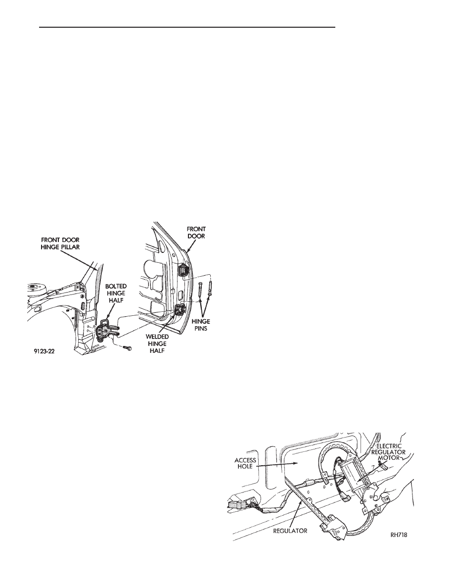
POWER WINDOW REGULATOR

REMOVAL (FIG. 15)

(1) Remove door trim panel.
(2) Remove silencer and water shield as necessary.
(3) Raise glass to 25 mm (1 in.) below full up posi-

tion and support glass to keep the glass from falling.
Disconnect battery negative cable.

(4) Remove bolts holding regulator to inner door

panel.

(5) Remove nuts holding lift plate to glass.
(6) Remove regulator assembly through access hole

in door.

INSTALLATION

Reverse the preceding operation.

Fig. 14 Front Door Assembly

Fig. 15 Power Window Regulator

Ä

AG-BODY

23 - 57

MANUAL WINDOW REGULATOR

REMOVAL (FIG. 16)

(1) Remove door trim panel.
(2) Remove silencer and water shield as necessary.
(3) Raise glass to 25 mm (1 in.) below full up posi-

tion and support glass to keep the glass from falling.

(4) Remove bolts holding regulator to inner door

panel.

(5) Remove nuts holding lift plate to glass.
(6) Remove regulator assembly through access hole

in door.

INSTALLATION

Reverse the preceding operation.

MANUAL WINDOW LIFT PLATE AND GUIDE

REMOVAL (FIG. 16)

(1) Remove door trim panel, silencer and water

shield.

(2) Raise glass enough to align lift plate to large

access hole in inner door panel.

(3) Remove nuts holding glass to lift plate.
(4) Separate glass from lift plate and allow glass to

rest on bottom of door.

(5) Remove bolt holding guide bar to upper door

frame.

(6) Remove bolts holding guide bar top inner door

panel.

(7) Slide regulator lift arm roller from lift plate

channel.

(8) Remove lift plate and guide bar through large

access hole in inner door panel.

INSTALLATION

Reverse the preceding operation.

DOOR GLASS

REMOVAL (FIG. 17)

(1) Remove door trim panel.
(2) Remove silencer and water shield.
(3) Raise door glass 100 mm (4 in.) from down po-

sition.

(4) Disconnect battery negative cable if equipped

with power windows.

(5) Loosen bolts holding glass stabilizers and guide

hook receiver to top of inner door frame.

(6) Remove nuts holding door glass to lift plate.
(7) Separate glass from lift plate and lift glass up-

ward from opening at top of door.

INSTALLATION

Reverse the preceding operation.

GLASS RUN WEATHERSTRIP

REMOVAL

(1) Remove door trim panel.
(2) Remove silencer and water shield as necessary.
(3) Remove side view mirror cover.
(4) Pull glass run weatherstrip from door frame

channel.

INSTALLATION

Reverse the preceding operation.

OUTSIDE DOOR LATCH RELEASE HANDLE

REMOVAL (FIG. 18)

(1) Remove door trim panel, silencer pad, and wa-

ter shield.

(2) Raise door glass to full up position.
(3) Disconnect security alarm switch and illumi-

nated entry switch from back of outside front door
latch release handle, if equipped. For additional in-
formation refer to Group 8Q, Vehicle Theft Security
System

(4) Disconnect lock rod and latch release rod from

door latch assembly.

Fig. 16 Manual Window Regulator

Fig. 17 Door Glass

23 - 58

AG-BODY

Ä

(5) Remove nuts holding outside door latch handle

to retainer bracket and separate bracket from door.

(6) Swing lock rod upward, parallel to back of

latch handle, and separate latch handle from door
panel.

INSTALLATION

Reverse the preceding operation.

INSIDE LATCH RELEASE HANDLE

REMOVAL

(1) Remove door trim panel.
(2) Remove screw holding handle to inner door

panel.

(3) Disconnect linkage rod from back of handle.
(4) Separate handle from door.

INSTALLATION

Reverse the preceding operation.

POWER DOOR LOCK ACTUATOR

REMOVAL (FIG. 19)

(1) Remove door trim panel. Remove silencer and

water shield as necessary.

(2) Raise door glass to the up position.
(3) Disconnect battery negative cable.
(4) Disconnect lock actuator linkage rod from door

latch.

(5) Remove bolts holding actuator to inner door

panel.

(6) Separate power door lock actuator from door.

INSTALLATION

Reverse the preceding operation.

SIDE VIEW MIRROR

REMOVAL (FIG. 20)

(1) Remove door trim panel.
(2) Disconnect power mirror wire connector.

(3) Remove covers to gain access to mirror attach-

ing nuts.

(4) Remove nuts holding mirror to door frame.
(5) Separate mirror from door frame.

INSTALLATION

Reverse the preceding operation.

DOOR GLASS OPENING MOULDING

REMOVAL

(1) Remove door trim panel.
(2) Remove door glass.
(3) Remove side view mirror.
(4) Disengage clips holding door glass opening

moulding to the door frame (Fig. 21).

(5) Remove screws holding door glass opening

moulding and belt weatherstrip to door belt flange
(Fig. 22).

(6) Remove the belt weatherstrip.
(7) Remove window opening moulding.

INSTALLATION

Reverse the preceding operation.

Fig. 18 Outside Door Latch Release Handle—Typical

Fig. 19 Power Door Lock Actuator

Fig. 20 Side View Mirror

Ä

AG-BODY

23 - 59

DOOR OPENING WEATHERSTRIPS

REMOVAL

(1) Remove interior trim as necessary to gain ac-

cess to door opening weatherstrip.

(2) Pull weatherstrip from pinch flange around

door opening.

INSTALLATION

(1) Locate the middle to the weatherstrip at the

center of the upper pinch flange. Push weatherstrip
onto pinch flange at the top corner near the B-pillar.

(2) When the weatherstrip has been installed down

the door opening to the sill pinch flange, mate the
ends of the weatherstrip together and finish install-
ing.

BODY SIDE MOULDINGS

STICK-ON BODY SIDE MOULDING REMOVAL
AND INSTALLATION

(1) Warm the effected stick-on moulding and body

metal to approximately 38°C (100°F) using a suitable
heat lamp or heat gun.

(2) Pull stick-on moulding from painted surface.
(3) Remove adhesive tape residue from painted

surface of vehicle.

(4) If moulding is to be reused, Remove tape resi-

due from moulding. Clean back of moulding with Mo-
par,

Super

Kleen

solvent

or

equivalent.

Wipe

moulding dry with lint free cloth. Apply new body
side moulding (two sided adhesive) tape to back of
moulding.

(5) Clean body surface with Mopar, Super Kleen

solvent or equivalent. Wipe surface dry with lint free
cloth.

(6) Apply a length of masking tape on the body,

parallel to the top edge of the moulding to use as a
guide, if necessary.

(7) Remove protective cover from tape on back of

moulding. Apply moulding to body below the mask-
ing tape guide.

(8) Remove masking tape guide and heat body and

moulding, refer to step one. Firmly press moulding to
body surface to assure adhesion.

BODY SIDE APPLIQUE

REMOVAL (FIG. 23)

DOOR APPLIQUE

(1) Remove rivets holding bottom or door applique

to door pinch flange using a 3 mm (0.125 in.) drill.

(2) Lift door applique upward to disengage appli-

que from retainer channel.

(3) Separate applique from door.

SILL APPLIQUE

(1) Remove push-in fasteners holding sill applique

to bottom of rocker panel.

(2) Remove push-in fasteners holding sill applique

to front and rear wheel lip openings.

(3) Lift sill applique upward to disengage applique

from retainer channels.

(4) Separate sill applique from vehicle.

INSTALLATION

Prime and touch-up bare metal surfaces before in-

stalling applique to avoid corrosion. Reverse the re-
moval operation.

Fig. 21 Window Opening Moulding

Fig. 22 Outer Belt Weatherstrip

Fig. 23 Body Side Applique

23 - 60

AG-BODY

Ä


Content   ..  160  161  162  163   ..