Chrysler Le Baron, Dodge Dynasty, Plymouth Acclaim. Manual - part 157


  Index      Chrysler     Chrysler Le Baron, Dodge Dynasty, Plymouth Acclaim - service repair manual 1993 year


Search            


Content   ..  155  156  157  158   ..


Chrysler Le Baron, Dodge Dynasty, Plymouth Acclaim. Manual - part 157


AC-VEHICLE BODY COMPONENT SERVICE

INDEX

page

page

A-Pillar and Roof Rail Mouldings

. . . . . . . . . . . . . 46

B-Pillar Trim Panel

. . . . . . . . . . . . . . . . . . . . . . . 46

Body Mouldings

. . . . . . . . . . . . . . . . . . . . . . . . . . 49

Cowl Panel Trim and Scuff Plates

. . . . . . . . . . . . 46

Door Frame Trim Moulding

. . . . . . . . . . . . . . . . . 41

Front Door and Hinge

. . . . . . . . . . . . . . . . . . . . . 41

Front Door Glass

. . . . . . . . . . . . . . . . . . . . . . . . 43

Front Door Latch

. . . . . . . . . . . . . . . . . . . . . . . . . 42

Front Door Trim Panel

. . . . . . . . . . . . . . . . . . . . 40

Front Door Water Shield

. . . . . . . . . . . . . . . . . . . 41

Front Door Window Regulator

. . . . . . . . . . . . . . . 42

Front End Splash Shields

. . . . . . . . . . . . . . . . . . 40

Front Seat Belts

. . . . . . . . . . . . . . . . . . . . . . . . . 47

Front Seats

. . . . . . . . . . . . . . . . . . . . . . . . . . . . . 48

Grille AC/C Body

. . . . . . . . . . . . . . . . . . . . . . . . . 38

Grille AC/D or AC/C-H Body

. . . . . . . . . . . . . . . . 37

Grille Extension Moulding

. . . . . . . . . . . . . . . . . . 37

Grille Opening Panel AC/C-Body

. . . . . . . . . . . . . 38

Grille Opening Panel AC/D and AC/C-H Body

. . . 37

Head Lining

. . . . . . . . . . . . . . . . . . . . . . . . . . . . . 45

Hood and Hinges

. . . . . . . . . . . . . . . . . . . . . . . . 38

Hood Latch and Release Cable

. . . . . . . . . . . . . . 39

Hood Latch Release Cable

. . . . . . . . . . . . . . . . . 39

Hood Ornament AC/C

. . . . . . . . . . . . . . . . . . . . . 38

Outside Door Handle

. . . . . . . . . . . . . . . . . . . . . . 42

Overhead Console

. . . . . . . . . . . . . . . . . . . . . . . . 45

Quarter Trim Panel

. . . . . . . . . . . . . . . . . . . . . . . 46

Rear Deck Filler Panel

. . . . . . . . . . . . . . . . . . . . 49

Rear Door and Hinge

. . . . . . . . . . . . . . . . . . . . . 44

Rear Door Frame Trim Moulding

. . . . . . . . . . . . . 43

Rear Door Glass

. . . . . . . . . . . . . . . . . . . . . . . . . 45

Rear Door Glass Lift Plate and Guide Bar

. . . . . 45

Rear Door Latch

. . . . . . . . . . . . . . . . . . . . . . . . . 44

Rear Door Outside Handle

. . . . . . . . . . . . . . . . . 44

Rear Door Silencer and Water Shield

. . . . . . . . . 43

Rear Door Trim Panel

. . . . . . . . . . . . . . . . . . . . . 43

Rear Door Window Regulator

. . . . . . . . . . . . . . . 45

Rear Seat Belts

. . . . . . . . . . . . . . . . . . . . . . . . . . 47

Rear Seats

. . . . . . . . . . . . . . . . . . . . . . . . . . . . . 49

Rear Shelf Trim Panel

. . . . . . . . . . . . . . . . . . . . . 47

Rear Window Glass

. . . . . . . . . . . . . . . . . . . . . . 50

Side View Mirror Trim Cover

. . . . . . . . . . . . . . . . 41

Trunk Lid

. . . . . . . . . . . . . . . . . . . . . . . . . . . . . . 50

Trunk Lid Hinge

. . . . . . . . . . . . . . . . . . . . . . . . . 51

Trunk Lid Torsion Bar

. . . . . . . . . . . . . . . . . . . . . 51

Vinyl Roof Bonnet

. . . . . . . . . . . . . . . . . . . . . . . . 49

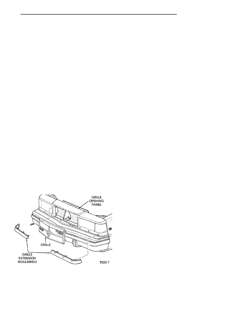
GRILLE AC/D or AC/C-H BODY

GRILLE REMOVAL (FIG. 1)

(1) Remove screws holding grille to grille opening

panel.

(2) Separate grille from vehicle.

GRILLE INSTALLATION

Reverse the preceding operation.

GRILLE EXTENSION MOULDING

REMOVAL (FIG. 1)

(1) Raise vehicle and support on safety stands if

necessary.

(2) Remove nuts holding moulding to grille open-

ing panel from behind fascia below headlamps.

(3) Separate moulding from vehicle.

INSTALLATION

Reverse the preceding operation.

GRILLE OPENING PANEL AC/D and AC/C-H BODY

GRILLE OPENING PANEL REMOVAL (FIG. 2)

(1) Remove grille.
(2) Disconnect wire connectors from all front end

lighting.

(3) Remove front end splash shields as necessary to

gain access to grille opening panel attaching nuts be-
hind front fenders.

(4) Remove nuts holding grille opening panel to

front fenders.

(5) Remove bolts holding grille opening panel to

center support brace behind grille.

(6) Separate grille opening panel from vehicle.

GRILLE OPENING PANEL INSTALLATION

Reverse the preceding operation.

Fig. 1 Grille—AC/D Body

Ä

AC-BODY

23 - 37

GRILLE AC/C BODY

GRILLE REMOVAL (FIG. 3)

(1) Loosen hidden screws holding grille to grille

opening panel at corners of grille. The screws are
captured in a clearance hole covered by a bracket be-
hind the grille.

(2) Pull grille forward from grille opening panel.

GRILLE INSTALLATION

Reverse the preceding operation.

HOOD ORNAMENT AC/C

HOOD ORNAMENT REMOVAL (FIG. 3)

(1) Remove grille.
(2) Locate hood ornament spring under grille open-

ing panel header.

(3) Compress hood ornament spring enough to

clear hooks on end of retaining wire.

(4) Squeeze retainer wire hooks together and push

hooks inside spring.

(5) Rotate

spring

counterclockwise

to

separate

spring from retainer.

(6) Separate hood ornament from grille opening

panel.

HOOD ORNAMENT INSTALLATION

Reverse the preceding operation.

GRILLE OPENING PANEL AC/C-BODY

For service procedures for headlamp related compo-

nents refer to Group 8L, Lamps.

REMOVAL (FIG. 4)

(1) Remove front bumper.
(2) Remove front end splash shields as necessary to

gain access to behind fenders.

(3) Remove nuts holding mouldings to front fend-

ers.

(4) Remove bolts holding mouldings to bottom of

grille opening panel and separate mouldings from ve-
hicle.

(5) Remove nuts holding grille opening panel to

front fenders.

(6) Disconnect concealed headlamp motor wire con-

nector.

(7) Disconnect headlamp wire connectors.
(8) Remove bolts holding grille opening panel to

radiator closure panel.

(9) Separate grille opening panel from vehicle.

INSTALLATION

Reverse the preceding operation.

HOOD AND HINGES

HOOD REMOVAL (FIG. 5)

(1) Raise hood to full up position.
(2) Disconnect the under hood lamp wire connec-

tor.

(3) Mark all bolt and hinge attachment locations

with a grease pencil or other suitable device to pro-
vide reference marks for installation. When install-

Fig. 2 Grille Opening Panel—AC/D Body

Fig. 3 Grille—AC/C Body

Fig. 4 Grille Opening Panel—AC/C Body

23 - 38

AC-BODY

Ä

ing hood, align all marks and secure bolts. The hood
should be aligned to 4 mm (0.160 in.) gap to the front
fenders and flush across the top surfaces along fend-
ers.

(4) Remove the top hood to hinge bolts and loosen

the bottom bolts until they can be removed by hand.

(5) With assistance of a helper at the opposite side

of the vehicle to support the hood, remove the bottom
hood to hinge bolts. Separate the hood from the ve-
hicle.

HOOD INSTALLATION

Reverse the preceding operation.

HOOD HINGE REMOVAL (FIG. 6)

(1) Support hood on the side that requires hinge

replacement.

(2) Mark all bolt and hinge attachment locations

with a grease pencil or other suitable device to pro-
vide reference marks for installation. When install-
ing hood hinge, align all marks and secure bolts. The
hood should be aligned to 4 mm (0.160 in.) gap to the
front fenders and flush across the top surfaces along
fenders. Shims can be added or removed under hood
hinge to achieve proper hood height.

(3) Remove hood to hinge attaching bolts.
(4) Remove hood hinge to front fender attaching

bolts and separate hinge from vehicle.

HOOD HINGE INSTALLATION

Reverse the preceding operation. If necessary, paint

new hinge before installation.

HOOD LATCH AND RELEASE CABLE

HOOD LATCH REMOVAL (FIG. 7)

(1) Raise hood top the full up position.
(2) Remove hood latch attaching bolts holding

latch to radiator closure panel and separate from ve-
hicle.

(3) Pry release cable casing attachment from slot

receiver on latch, disengage cable end from latch arm
hook.

HOOD LATCH INSTALLATION

Reverse the preceding operation.

HOOD LATCH RELEASE CABLE

REMOVAL (FIG. 8)

(1) Raise hood to the full up position.
(2) Remove push-in fasteners holding hood latch

cover to radiator closure panel and separate cover
from vehicle, if equipped.

(3) Disconnect hood release cable casing and cable

end from hood latch assembly. Refer to Hood Latch
Removal procedure in this section.

(4) Remove hood latch release cable handle attach-

ing bolts from under left lower edge of instrument
panel.

(5) Disengage release cable rubber grommet from

engine compartment dash panel behind instrument
panel.

(6) Rout cable assembly through engine compart-

ment around battery, under fender lip, under relay
bank, and under wiring harnesses, toward dash

Fig. 5 Hood Remove or Install—Typical

Fig. 6 Hood Hinge Assembly—Typical

Ä

AC-BODY

23 - 39

panel. Push cable through access hole in dash panel
under the brake master cylinder, into passenger com-
partment.

INSTALLATION

Reverse the preceding operation.

FRONT END SPLASH SHIELDS

FRONT WHEELHOUSE SPLASH SHIELD
REMOVAL (FIG. 9)

(1) Hoist vehicle and support on suitable safety

stands.

(2) Remove front wheel assembly.
(3) Remove push-in fasteners holding front wheel-

house splash shield to fender opening lip and inner
wheelhouse area.

(4) Separate wheelhouse splash shield from vehi-

cle.

FRONT WHEELHOUSE SPLASH SHIELD
INSTALLATION

Reverse the preceding operation.

TRANSAXLE SPLASH SHIELD REMOVAL (FIG.
9)

(1) Remove one front wheelhouse splash shield

push-in fastener and separate wheelhouse splash
shield from transaxle splash shield.

(2) Remove transaxle splash shield attaching bolts

and separate transaxle splash shield from vehicle.

TRANSAXLE SPLASH SHIELD INSTALLATION

Reverse the preceding operation.

ENGINE DRIVE BELT SPLASH SHIELD
REMOVAL (FIG. 10)

(1) Hoist vehicle and support on suitable safety

stands.

(2) Remove bolts holding engine drive belt splash

shield to right frame rail.

(3) Separate drive belt splash shield from vehicle.

ENGINE DRIVE BELT SPLASH SHIELD
INSTALLATION

Reverse the preceding operation.

FRONT DOOR TRIM PANEL

TRIM PANEL REMOVAL (FIG. 11)

(1) Remove speaker grille. Disconnect power seat

switch wire connector, if equipped.

(2) Remove courtesy lamp lens.
(3) Remove screws holding arm rest to inner door

panel.

(4) Remove hidden screws from carpet holding trim

panel to inner door panel.

Fig. 7 Hood Latch Assembly

Fig. 8 Hood Latch Release Cable Assembly

Fig. 9 Front Wheelhouse and Transaxle Splash

Shields

23 - 40

AC-BODY

Ä


Content   ..  155  156  157  158   ..