Chrysler Le Baron, Dodge Dynasty, Plymouth Acclaim. Manual - part 155


  Index      Chrysler     Chrysler Le Baron, Dodge Dynasty, Plymouth Acclaim - service repair manual 1993 year


Search            


Content   ..  153  154  155  156   ..


Chrysler Le Baron, Dodge Dynasty, Plymouth Acclaim. Manual - part 155


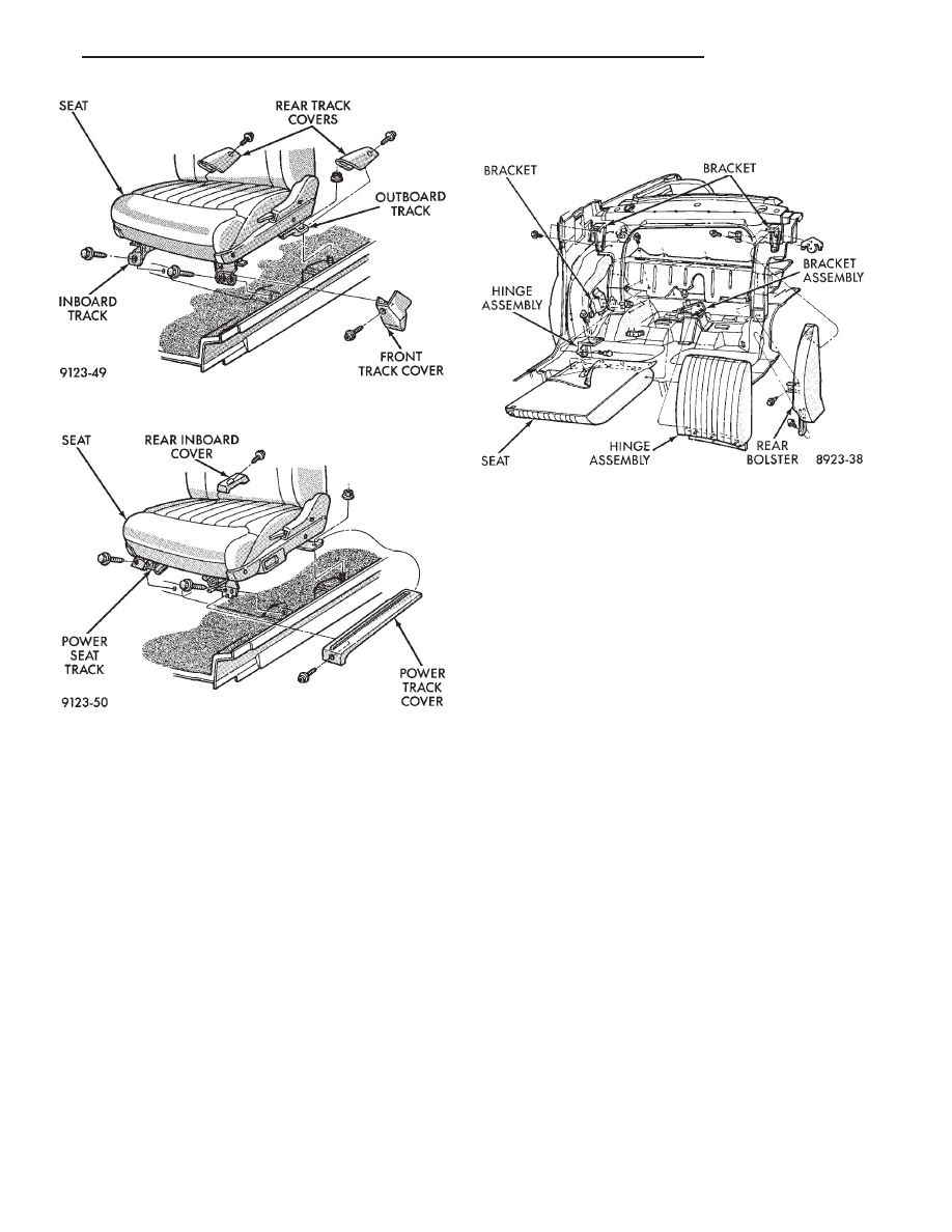
REAR SEAT BACK REMOVAL (FIG. 44)

(1) Hinge seat back forward and disengage push-in

fasteners holding carpet backing to trunk floor.

(2) Remove bolts holding outboard hinge pivot

bracket to seat back.

(3) Pull seat back outward to disengage inboard

pivot and separate from vehicle.

REAR SEAT BACK INSTALLATION

Reverse the preceding operation.

SEAT BACK BOLSTER CUSHION REMOVAL
(FIG. 44)

(1) Remove rear seat cushion and back as neces-

sary.

(2) Remove bolts holding outboard back bolster to

quarter panel.

(3) Lift bolster upward to disengage hook retainer

on back of bolster and separate from vehicle.

SEAT BACK BOLSTER CUSHION
INSTALLATION

Reverse the preceding operation

FRONT CENTER CONSOLE

REMOVAL (FIG. 45)

(1) Position front seats full forward.
(2) Remove access hole plugs on sides of center

arm rest riser and remove bolts holding riser to floor
bracket.

(3) Remove coin holder and remove screws holding

arm rest riser to front console.

(4) Position front seats full rearward.
(5) Remove radio bezel from instrument panel. Re-

fer to Group 8E, Instrument Panel. Remove screws
holding console to instrument panel.

(6) Remove screws holding console to lower instru-

ment panel rail.

(7) Remove screws and disengage hook and loop

fastener holding carpet panels to sides of console and
separate panels from console.

(8) Remove screws holding console to forward floor

mounting bracket.

(9) Remove set screw holding gear selector knob to

shift lever and pull knob from shifter on vehicles
with automatic transaxle.

(10) Lift forward edge of PRNDL cover and sepa-

rate cover from console on vehicles with automatic
transaxle.

(11) Lift gear shift boot adapter from console and

push adapter through opening in console on vehicles
with manual transaxle.

(12) Separate console from floor and remove from

vehicle.

Fig. 42 Manual Front Seat

Fig. 43 Power Front Seat

Fig. 44 Rear Seat Cushion and Back

Ä

AA-BODY

23 - 29

INSTALLATION

Reverse the preceding operation. On vehicles with

automatic transaxle, verify gear selector indicator
adjustment before returning vehicle to use.

FLOOR CARPET

REMOVAL (FIG. 46)

(1) Remove cowl trim panels and scuff plates.
(2) Remove front seats and inboard seat belts.
(3) Remove center arm rest and front console.
(4) Remove outboard seat belt lower attaching

bolts.

(5) Remove rear seat cushion.
(6) Pull carpet from under B-pillar trim covers.
(7) Fold carpet and remove through front door

opening.

INSTALLATION

Reverse the preceding operation.

OVERHEAD CONSOLE

REMOVAL (FIG. 47)

(1) Remove screws holding overhead console to re-

inforcement bracket.

(2) Slide overhead console rearward to separate re-

inforcement bracket retainer tab from console.

(3) Lower console from roof and disconnect wire

connectors.

INSTALLATION

Reverse The preceding operation.

HEAD LINING

REMOVAL (FIG. 48)

(1) Disconnect battery negative cable.
(2) Pull dome lamp downward to disengage from

retaining ring in head lining. Separate lens from
lamp body and remove bulb. Separate bulb holder
from lamp body. Remove attaching screw holding re-
taining ring to roof bow.

(3) Remove screws holding coat hooks to roof above

rear doors.

(4) Remove roof rail and A-pillar mouldings.
(5) Remove screws holding sun visors to roof

header and disconnect wire connector, if equipped.
Remove inboard sun visor hangers.

(6) Remove overhead console, if equipped.
(7) Pull front reading lamp downward to disengage

from retaining ring in head lining and disconnect
wire connector. Remove screws holding retaining
ring to roof header.

(8) Remove pinch welt holding headlining to sun

roof opening, if equipped.

(9) Remove inside rear view mirror from wind-

shield bracket if necessary.

(10) Disengage hook and loop fasteners holding

head lining to roof above rear window and slide head
lining forward about 25 mm (1 in.).

Fig. 45 Front Center Console

Fig. 46 Floor Carpet and Silencers

Fig. 47 Overhead Console

23 - 30

AA-BODY

Ä

(11) Shift the front of head lining to one side to

pull head lining from behind B-pillar trim. Pull head
lining from behind other B-pillar trim.

(12) Allow front of head lining to drop downward.

Slide head lining forward from behind quarter panel
trim.

(13) Remove head lining from vehicle.

INSTALLATION

Reverse the preceding operation.

SUN ROOF WEATHERSTRIP

REMOVAL (FIG. 49)

(1) Remove sun roof sunshade and glass. Refer to

Owner’s Manual for instructions.

(2) Pull weatherstrip from pinch flange around sun

roof opening.

INSTALLATION

Reverse the preceding operation.

SUN ROOF AIR DEFLECTOR

REMOVAL (FIG. 49)

(1) Remove sun roof sunshade and glass. Refer to

Owner’s Manual for instructions.

(2) Disengage snap-on linkage at rear of air deflec-

tor in sun roof opening.

(3) Remove screws holding air deflector to front of

sun roof opening.

INSTALLATION

Reverse the preceding operation.

SUN ROOF DRAIN TUBES

REMOVAL (FIG. 49)

(1) Remove head lining as necessary.
(2) Remove A-pillar or B-pillar trim covers as nec-

essary.

(3) Remove cowl panel and sill plate trim as neces-

sary.

(4) Disconnect effected drain tube from nipple at

sun roof opening.

(5) Pull drain tube upward to remove from pillar

involved.

INSTALLATION

Reverse the preceding operation. Route the tube to

avoid kinks or puncture from sharp edges.

VINYL ROOF BONNET

REMOVAL (FIG. 50)

(1) Remove quarter panel trim covers.
(2) Remove head lining.
(3) Remove nuts holding transverse roof moulding

to roof panel and separate moulding from vehicle.

(4) Remove nuts holding vinyl top bonnet to roof.
(5) Remove rear deck filler panel.
(6) Remove screws holding rear window opening

lower valance to body.

(7) Disengage hook and loop fasteners holding vi-

nyl top bonnet to quarter panels.

(8) Pull vinyl top bonnet away from top panel to

separate bonnet from anti-flutter sealer holding bon-
net to roof.

INSTALLATION

(1) Clean anti-flutter sealer from roof surface and

inside of vinyl roof bonnet.

(2) Apply a 20 mm (0.75 in.) bead of anti-flutter

sealer across the roof panel at the mid point between
the front of the bonnet and rear of roof.

(3) Apply a 20 mm (0.75 in.) by 150 mm (6 in.)

bead of anti-flutter sealer down each roof side panel
at mid point between the door opening and rear of
roof.

(4) Place the bonnet into position on the roof panel

and align to proper fit.

(5) Reverse the removal operation.

REAR DECK FILLER PANEL

REMOVAL (FIG. 51)

(1) Raise truck lid to full up position.
(2) Remove screws holding rear deck filler panel to

body in the front trunk opening gutter.

(3) Close trunk lid, do not latch.
(4) Lift filler panel upward and separate from ve-

hicle.

Fig. 48 Head Lining

Ä

AA-BODY

23 - 31

INSTALLATION

Reverse the preceding operation.

REAR WINDOW GLASS

REMOVAL (FIG. 52)

The rear window moulding often cannot be sal-

vaged after removal operation is completed. Verify
moulding availability from the parts supplier before
removing moulding.

(1) Remove rear deck filler panel.
(2) Pull rear window moulding from between glass

and roof panel.

Fig. 49 Sun Roof

Fig. 50 Vinyl Roof Bonnet

Fig. 51 Rear Deck Filler Panel

23 - 32

AA-BODY

Ä


Content   ..  153  154  155  156   ..