Chrysler Le Baron, Dodge Dynasty, Plymouth Acclaim. Manual - part 99


  Index      Chrysler     Chrysler Le Baron, Dodge Dynasty, Plymouth Acclaim - service repair manual 1993 year


Search            


Content   ..  97  98  99  100   ..


Chrysler Le Baron, Dodge Dynasty, Plymouth Acclaim. Manual - part 99


TRANSAXLE

CONTENTS

page

page

41TE FOUR SPEED AUTOMATIC TRANSAXLE . 85
41TE FOUR SPEED TRANSAXLE HYDRAULIC

SCHEMATICS

. . . . . . . . . . . . . . . . . . . . . . . . 170

41TE ON-BOARD DIAGNOSTICS

. . . . . . . . . . 145

A-523, A-543, and A-568 MANUAL

TRANSAXLE

. . . . . . . . . . . . . . . . . . . . . . . . . . . 1

SPECIFICATIONS

. . . . . . . . . . . . . . . . . . . . . . 183

THREE SPEED TORQUEFLITE AUTOMATIC

TRANSAXLE

. . . . . . . . . . . . . . . . . . . . . . . . . . 35

THREE SPEED TRANSAXLE HYDRAULIC

SCHEMATICS

. . . . . . . . . . . . . . . . . . . . . . . . 162

A-523, A-543, and A-568 MANUAL TRANSAXLE

INDEX

page

page

Bearing Adjustment Procedure

. . . . . . . . . . . . . . 31

Differential Bearing Preload Adjustment

. . . . . . . . 33

Gearshift Linkage Adjustment (Cable Operated)

. . 2

General Information

. . . . . . . . . . . . . . . . . . . . . . . . 1

In-Car Transaxle Disassemble/Assemble

. . . . . . . . 4

Out of Car Transaxle—Disassemble and Assemble . 6
Subassembly-Recondition

. . . . . . . . . . . . . . . . . . 15

Transaxle Removal and Installation

. . . . . . . . . . . . 5

GENERAL INFORMATION

Safety goggles should be worn at all times

when working on these transaxles. All manual
transaxles use SAE 5W-30 engine oil, meeting SG
and/or SG-CC qualifications, as the lubricant in order
to reduce wear.

This 5-speed manual transaxles combine gear reduc-

tion, ratio selection, and differential functions in one
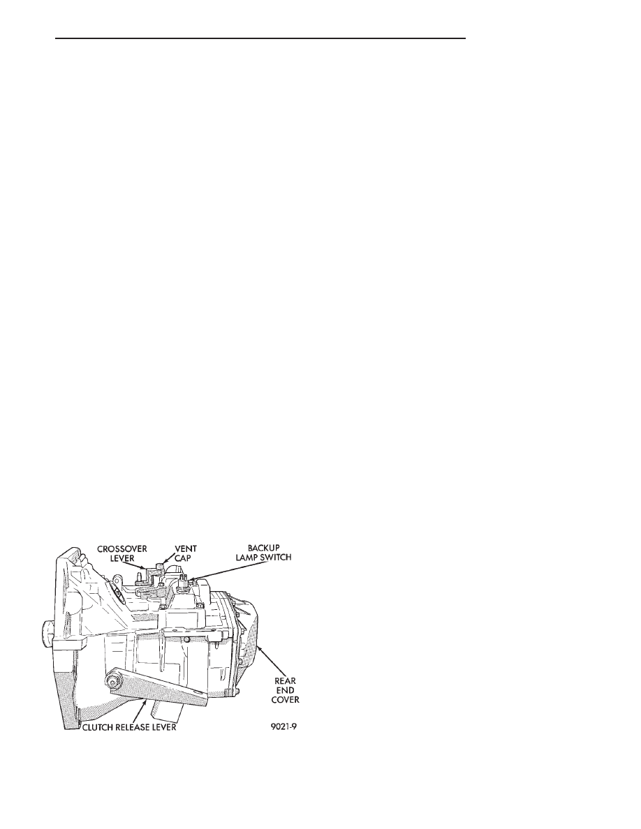
unit. It is housed in a die-cast aluminum case (Fig. 1).

All shift forks are cast iron. Do not interchange 1-2

or 5th shift fork pads with the 3-4 shift fork pads.
All synchronizers use a winged strut design that
prevents the struts from popping out of position.

If any synchronizer is to be disassembled, mark

all parts so that they will be reassembled in the
same position.

CAUTION: 1-2 synchronizer assembly components
must NOT be interchanged with any other synchro-
nizer assembly. Do not interchange with previous
model years transaxles; they will NOT function cor-
rectly.

A-523 AND A-543 MANUAL TRANSAXLE

The A-523 manual transaxle is used in all 4-cylinder

applications, except high output turbocharged engines.
The A-543 manual transaxle is used only with V-6
engines.

To reduce wear, the manual transaxle uses SAE

5W-30 engine oil as the lubricant.

Gear ratios for the A-523 and A-543 are as follows:

1st—3.31, 2cd—2.06, 3rd—1.36, 4th—0.97, 5th—0.71,
Reverse—3.14. The final drive ratio is 3.77.

CAUTION: All gears and shafts must not be inter-
changed with previous model years; they will not
function correctly.

Fig. 1 External Transaxle Components

Ä

TRANSAXLE

21 - 1

A-568 HEAVY—DUTY MANUAL TRANSAXLE

The greater torque of the high output turbo engines

require a stronger transmission. It includes a die-cast
aluminum case and a stronger, coarse-pitch gear set. It
has five forward speed ratios and reverse. Gear ratios
are

as

follows:

1st—3.31,

2nd—1.89,

3rd—1.28,

4th—0.94, 5th—0.71, Reverse—3.14. Final drive ratio
of 3.85 was selected for maximum performance. All
forward gears are synchronized.

To reduce wear, this transaxle, in common with other

manual transaxles, uses SAE 5W-30 engine oil as the
lubricant.

IDENTIFICATION

A-523, A-543, and A-568: the transaxle model, assem-

bly number, build date, and final-drive ratio are
stamped on a tag that is attached to the top of the
transaxle (Fig. 2).

Certain

transaxle

assemblies

utilize

high-

strength Steel in various gears to provide adequate
life in heavy-duty applications. Therefore, it is im-
perative that the correct transaxle assembly
number is utilized when ordering service parts.
Also, be sure to reinstall this tag whenever it is
removed, so the information is available for future
service.

The last eight digits of the Vehicle Identification

Number (V.I.N.) are stamped on a raised boss on top
of the clutch housing area.

GEARSHIFT LINKAGE ADJUSTMENT (CABLE
OPERATED)

Before replacing the gearshift selector cable or

crossover cable for a hard-shifting complaint, dis-
connect both cables at the transaxle (Fig. 3). Then,
from the driver’s seat, manually operate the gear-

Fig. 2 A-523, A-543, and A-568 Transaxle

Identification

Fig. 3 Gearshift Mechanism

21 - 2

TRANSAXLE

Ä

shift lever through all gear ranges. If the gearshift
lever moves smoothly, the cable(s) should NOT be re-
placed. If the gear lever binds replace the cable that
is causing the binding condition.

(1) Working over the left front fender, remove the

lock pin from the transaxle gearshift (selector shaft)
housing (Fig. 4).

(2) Reverse the lock pin (so long end is down) and

insert lock pin into same threaded hole. A hole in the
selector shaft will align with the lock pin, allowing
the lock pin to be screwed into the housing. This op-
eration locks the selector shaft in the 3-4 neutral po-
sition.

(3) Remove or install gearshift knob (Fig. 5 or 6).

(4) Remove or install boot (Fig. 7) or console.

(5) Remove or install selector and crossover cables

(Fig. 8 or 9).

Cable attachment clips must be installed from

the side. Install cable fittings to shifter pins by
pushing with thumb.

Fig. 4 Manual Transaxle Pinned in the Neutral

Position to Adjust Gearshift

Fig. 5 Remove Gearshift Knob

Fig. 6 Install Gearshift Knob

Fig. 7 Remove or Install Boot

Fig. 8 Remove Cables

Ä

TRANSAXLE

21 - 3

CAUTION: Be sure crossover bellcrank does NOT
move when tightening adjusting screw (Fig. 10).

CAUTION: Proper torque to the crossover cable ad-
justing screw is very important (Fig. 10).

(6) Remove lock pin from gearshift housing and re-

install lock pin (so long end is up) in gear shift hous-
ing. Tighten lock pin to 8 N

Im (70 in. lbs.).

(7) Check for shift into first and reverse.
(8) Gearshift mechanism and cables are now func-

tioning properly.

IN-CAR TRANSAXLE DISASSEMBLE/ASSEMBLE

The following items can be serviced without remov-

ing the transaxle from the vehicle:
• Gear shift housing

• Synchronizers

• Intermediate shaft speed gears

• Input shaft

• Reverse idler gear and shaft

• Shift forks and pads

• Shift rails

• Roller detents

• Speedometer pinion

• All external covers

Observe following procedure:
(1) Disconnect negative cable from battery.
(2) Remove both shift cables from shift cover levers.
(3) Remove left front wheel and tire assembly and

left splash shield.

(4) Place drain pan under transaxle and remove

transaxle rear end cover.

(5) Push out the fifth fork roll pin and slide the fifth

fork and synchronizer sleeve off the rail/hub.

(6) Remove the fifth hub snap ring, hub assembly

and speed gear.

(7) Remove fifth gear nut and fifth input gear.
(8) Remove the bearing retainer plate, interlock

plate and shuttles.

CAUTION: Before removing the gearshift housing
assembly, reverse the lock pin (so the long end is
down) and insert lock pin into the same threaded
hole. This procedure will save time when the gear
shift housing assembly is reinstalled.

(9) Remove selector shaft housing bolts (note the two

pilot bolts) and remove housing.

(10) Remove roller detents and springs, noting that

the rollers align with the shift rails.

(11) Push out the 1-2 and 3-4 lug roll pins, remove

the reverse pivot lever and fifth rail C-Clip. If a roll
pin or C-Clip falls, be sure to remove it from the
bottom of the case.

(12) Pull out the fifth shift rail and remove the fifth

shift lug and interlock pin.If the pin falls, be sure to
remove it from the bottom of the case.

(13) Remove the intermediate shaft ball bearing

snap ring and the bearing support plate.

(14) Remove reverse shift rail and lug assembly.
(15) Remove the reverse idler shaft and gear assem-

bly.

(16) Rotate the 1-2 shift lug and rail, and 3-4 shift

lug towards the front of the vehicle.

(17) Firmly grasp both the input and intermediate

shaft assemblies and pull them out of the transmission
with the 1-2 and 3-4 shift rails, lugs and forks.

The differential assembly can only be serviced

by removing the complete transaxle from the
vehicle because bearing preload must be reset.

The components listed in the first paragraph can now

be serviced. Refer to the appropriate subassembly
recondition 
section.

To reassemble the transaxle in the vehicle, reverse

the above procedure using the proper sealants. Fill the
transaxle with SAE 5W-30 engine oil to the bottom of
the fill hole in the end cover.

Fig. 9 Install Cables

Fig. 10 Adjusting Crossover Cable

21 - 4

TRANSAXLE

Ä


Content   ..  97  98  99  100   ..