Chrysler Le Baron, Dodge Dynasty, Plymouth Acclaim. Manual - part 95
AIR LINE FITTINGS
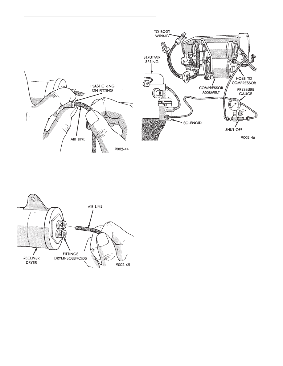
To remove an air supply line from an air compres-
sor assembly air line fitting. Push in (toward re-
ceiver dryer) on the plastic ring of the receiver dryer
air supply air line fitting. While holding in the air
line fitting on the receiver dryer pull the air supply
line strait out of the fitting (Fig. 6).
The fitting has a unique push-in feature. A brass
type collet locks the air line in place. One rubber
O-Ring seals the air line to prevent air leakage. To
attach air line, just push into fitting (Fig. 7).
AIR CHECK, RESIDUAL
The air dryer has a valving arrangement that
maintains 172 to 276 kPa (25 to 40 psi).
To test this function, perform the following proce-
dure:
(1) Remove the air line from the dryer and strut or
spring. Attach a piece of bulk nylon tubing to one
side of a Pressure Gauge (0-300 psi), and to the strut/
spring solenoid (Fig. 8).
(2) Attach another piece of nylon tubing from the
dryer (compressor) to other side of the pressure
gauge.
A compression ball sleeve nut and sleeve for 3/16
inch tubing with ball sleeve connector and an inter-
nal pipe T-fitting. Can be used to attach the tubing
to the pressure gauge.
(3) Activate compressor by grounding pin 508 to
pin x 20 (See Control Module Connector), cycle unit
and read actual air pressure. Pressure of 172 to 276
kPa (25 to 40 psi) indicates that the system and com-
pressor is acceptable.
COMPRESSOR PERFORMANCE TEST
This test can be performed on the vehicle to evalu-
ate compressor current draw, pressure output, and
leak down.
(1) Disconnect the compressor motor wiring har-
ness connector.
(2) Disconnect air line between dryer and strut or
spring solenoid.
(3) Connect an air pressure gauge into the system
(Fig. 8).
(4) Connect an ammeter in series between the red
wire terminal on compressor connector and a 12 volt
power source. Also, connect a ground wire from the
black wire terminal on the compressor connector to a
good ground on the frame (Fig. 9)
(5) If the current draw to the compressor motor ex-
ceeds 30 amperes, replace the compressor assembly.
AIR LEAK CHECK
(1) Check all air line to connector joints.
• Air line to compressor connectors.
• Air line to solenoid.
(2) Check the rubber membranes.
• Front struts.
• Rear springs.
Fig. 6 Release Air Line from Fitting
Fig. 7 Push Air Line into Fitting
Fig. 8 Pressure Gauge Installed in System
Ä
SUSPENSION AND DRIVESHAFTS
2 - 77