Chrysler Le Baron, Dodge Dynasty, Plymouth Acclaim. Manual - part 42


  Index      Chrysler     Chrysler Le Baron, Dodge Dynasty, Plymouth Acclaim - service repair manual 1993 year


Search            


Content   ..  40  41  42  43   ..


Chrysler Le Baron, Dodge Dynasty, Plymouth Acclaim. Manual - part 42


• Manifold Absolute Pressure (MAP) Sensor

• Oxygen Sensor

• SCI Receive

• Speed Control System Controls

• Throttle Position Sensor

• Vehicle Speed Sensor

PCM Outputs:

• Air Conditioning Clutch Relay

• Generator Field

• Idle Air Control Motor

• Auto Shutdown (ASD) Relay

• Barometric Read Solenoid

• Canister Purge Solenoid

• Malfunction Indicator Lamp (Check Engine Lamp)

• Data Link Connector

• Fuel Injectors

• Ignition Coil

• Radiator Fan Relay

• Speed Control Solenoids

• Tachometer Output

• Wastegate Solenoid

Based on inputs it receives, the PCM adjusts fuel

injector pulse width, idle speed, ignition spark ad-
vance, ignition coil dwell and canister purge opera-
tion. The PCM regulates operation of the cooling fan,
A/C and speed control systems. The PCM changes
generator charge rate by adjusting the generator
field.

The PCM adjusts injector pulse width (air-fuel ra-

tio) based on the following inputs.
• battery voltage

• engine coolant temperature

• exhaust gas content

• engine speed (crankshaft position sensor)

• manifold absolute pressure

• throttle position

The PCM adjusts ignition timing based on the fol-

lowing inputs.
• engine coolant temperature

• knock sensor

• engine speed (crankshaft position sensor)

• manifold absolute pressure

• throttle position

The Automatic Shut Down (ASD) and Fuel Pump

relays are mounted externally, but turned on and off
by the PCM through the same circuit.

The camshaft position sensor and crankshaft posi-

tion sensor signals are sent to the PCM. If the PCM
does not receive both signals within approximately
one second of engine cranking, it deactivates the
ASD relay and fuel pump relay. When these relays
are deactivated, power is shut off to the fuel injector,
ignition coil, oxygen sensor heating element and fuel
pump.

The

PCM

contains

a

voltage

converter

that

changes battery voltage to a regulated 8.0 volts. The
8.0 volts power the camshaft position sensor, crank-

shaft position sensor and vehicle speed sensor. The
PCM also provides a 5.0 volts supply for the coolant
temperature sensor, manifold absolute pressure sen-
sor and throttle position sensor.

AIR CONDITIONING SWITCH SENSE—PCM INPUT

When the air conditioning or defrost switch is put

in the ON position and the low pressure and high
pressure switches are closed, the PCM receives an in-
put for air conditioning. After receiving this input,
the PCM activates the A/C compressor clutch by
grounding the A/C clutch relay. The PCM also ad-
justs idle speed to a scheduled RPM to compensate
for increased engine load.

BATTERY VOLTAGE—PCM INPUT

The PCM monitors the battery voltage input to de-

termine fuel injector pulse width and generator field
control. If battery voltage is low the PCM will in-
crease injector pulse width (period of time that the
injector is energized).

BRAKE SWITCH—PCM INPUT

When the brake switch is activated, the PCM re-

ceives an input indicating that the brakes are being
applied. After receiving this input, the PCM vents
the speed control servo. Venting the servo turns the
speed control system off. The brake switch is
mounted on the brake pedal support bracket.

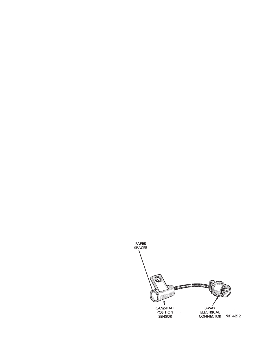
CAMSHAFT POSITION SENSOR—PCM INPUT

Fuel injection synchronization and cylinder identi-

fication are provided through the camshaft position
sensor (Fig. 3). The sensor generates pulses. The
pulse are the input sent to the PCM. The PCM inter-
prets the camshaft position sensor input along with
the crankshaft position sensor input to determine
crankshaft position. The PCM uses crankshaft posi-
tion sensor input to determine injector sequence and
ignition timing.

Fig. 3 Camshaft Sensor

Ä

FUEL SYSTEMS

14 - 85

The camshaft position sensor senses when a notch in

the camshaft gear passes beneath it (Fig. 4). When
metal aligns with the sensor, voltage goes low (less
than 0.3 volts). When a notch aligns with the sensor,
voltage spikes high (5.0 volts). As a group of notches
pass under the sensor, the voltage switches from low
(metal) to high (notch) then back to low. The number of
notches determine the amount of pulses. If available,
an oscilloscope can display the square wave patterns of
each timing events.

Top dead center (TDC) does not occur when notches

on the camshaft sprocket pass below the cylinder. TDC
occurs after the camshaft pulse (or pulses) and after
the 4 crankshaft pulses associated with the particular
cylinder.

The camshaft position sensor is mounted on the top

of the cylinder head (Fig. 5). The bottom of the sensor
is positioned above the camshaft sprocket. The dis-
tance between the bottom of sensor and the
camshaft sprocket is critical to the operation of
the system. When servicing the camshaft posi-
tion sensor, refer to the 2.2L Turbo III Multi-Port
Fuel Injection—Service Procedures section in
this Group.

CHARGE AIR TEMPERATURE SENSOR—PCM IN-
PUT

The charge air temperature sensor is mounted to

intake manifold. The sensor measures the temperature
of the air-fuel mixture (Fig. 6). This information is used
by the PCM to modify air/fuel mixture and turbo-
charger boost level.

ENGINE COOLANT TEMPERATURE SENSOR—PCM
INPUT

The coolant temperature sensor is a variable resis-

tor with a range of -40°C to 128°F (-40°F to 265°F).
The sensor is installed into the thermostat housing
(Fig. 7).

The PCM supplies 5.0 volts to the coolant temper-

ature sensor. The sensor provides an input voltage to
the PCM. The PCM determines engine operating
temperature from this input. As coolant temperature
varies, the sensor resistance changes resulting in a
different input voltage to the PCM.

Based on the coolant sensor and charge air temper-

ature sensor inputs the PCM changes certain operat-
ing schedules until the engine reaches operating
temperature. While the engine warms up, the PCM
demands slightly richer air-fuel mixtures, lower
boost levels, revised spark advance and higher idle
speeds.

Fig. 5 Camshaft Position Sensor Location

Fig. 6 Charge Air Temperature Sensor

Fig. 4 Camshaft Gear

14 - 86

FUEL SYSTEMS

Ä

CRANKSHAFT POSITION SENSOR—PCM INPUT

The crankshaft position sensor (Fig. 8) senses slots

cut into the flywheel. There are a 2 sets of slots.
Each set contains 4 slots, for a total of 8 slots (Fig.
9). Basic timing is set by the position of the last slot
in each group. Once the PCM senses the last slot, it
determines crankshaft position (which piston will
next be at TDC) from the camshaft position sensor
input. The 4 pulses generated by the crankshaft po-
sition sensor represent the 69°, 49°, 29°, and 9° BTDC
marks. It may take the PCM one engine revolution
to determine crankshaft position. The Turbo III en-
gine uses a fixed ignition system. Base timing is not
adjustable.

The PCM uses the crankshaft position sensor input

to determine injector sequence and ignition timing.
Once crankshaft position has been determined, the
PCM begins energizing the injectors in sequence.

The crankshaft position sensor is located in the

transaxle housing, below the throttle body (Fig. 10).
The bottom of the sensor is positioned next to the
drive plate. The distance between the bottom of

sensor and the drive plate is critical to the oper-
ation of the system. When servicing the crank-
shaft position sensor, refer to the 2.2L Turbo III
Multi-Port Fuel Injection—Service Procedures
section in this Group.

KNOCK SENSOR—PCM INPUT

The knock sensor generates a signal when spark

knock occurs in the combustion chambers. The sensor
can detect detonation in the cylinders. The sensor
provides information used by the PCM to modify
spark advance and boost schedules in order to elimi-
nate detonation.

The knock sensor is installed into the engine, be-

hind the PCV breather/separator (Fig. 11).

MANIFOLD ABSOLUTE PRESSURE (MAP)
SENSOR—PCM INPUT

The PCM supplies 5 volts to the MAP sensor. The

Map sensor converts intake manifold pressure into
voltage. The PCM monitors the MAP sensor output
voltage. As vacuum increases, MAP sensor voltage
decreases proportionately. Also, as vacuum decreases,
MAP sensor voltage increases proportionately.

Fig. 7 Coolant Temperature Sensor

Fig. 8 Crankshaft Position Sensor

Fig. 9 Timing Slots

Fig. 10 Crankshaft Position Sensor Location

Ä

FUEL SYSTEMS

14 - 87

During cranking, before the engine starts running,

the PCM determines atmospheric air pressure from
the MAP sensor voltage. While the engine operates,
the PCM determines intake manifold pressure and
barometric pressure from the MAP sensor voltage.
Based on MAP sensor voltage and inputs from other
sensors, the PCM adjusts spark advance, air/fuel
mixture and controls the turbocharger wastegate.

The MAP sensor (Fig. 12) mounts underhood on

the right side of the engine compartment. The sensor
connects electrically to the PCM.

HEATED OXYGEN SENSOR (O

2

SENSOR)—PCM

INPUT

The O

2

sensor is located in the turbocharger outlet

and provides an input voltage to the PCM (Fig. 13).
The input tells the PCM the oxygen content of the
exhaust gas. The PCM uses this information to fine
tune the air-fuel ratio by adjusting injector pulse
width.

The O

2

sensor produces voltages from 0 to 1 volt,

depending upon the oxygen content of the exhaust
gas in the exhaust manifold. When a large amount of

oxygen is present (caused by a lean air-fuel mixture),
the sensor produces a low voltage. When there is a
lesser amount present (rich air-fuel mixture) it pro-
duces a higher voltage. By monitoring the oxygen
content and converting it to electrical voltage, the
sensor acts as a rich-lean switch.

The oxygen sensor is equipped with a heating ele-

ment that keeps the sensor at proper operating tem-
perature during all operating modes. Maintaining
correct sensor temperature at all times allows the
system to enter into closed loop operation sooner.
Also, it allows the system to remain in closed loop
operation during periods of extended idle.

In Closed Loop operation the PCM monitors the O

2

sensor input (along with other inputs) and adjusts
the injector pulse width accordingly. During Open
Loop operation the PCM ignores the O

2

sensor input.

The PCM adjusts injector pulse width based on pre-
programmed (fixed) values and inputs from other
sensors.

SPEED CONTROL—PCM INPUT

The speed control system provides four separate

voltages (inputs) to the PCM. The voltages corre-
spond to the On/Off, Set, and Resume.

The speed control ON voltage informs the PCM

that the speed control system has been activated.
The speed control SET voltage informs the PCM that
a fixed vehicle speed has been selected. The speed
control RESUME voltage indicates the previous fixed
speed is requested. The speed control OFF voltage
tells the PCM that the speed control system has de-
activated. Refer to Group 8H for further speed con-
trol information.

THROTTLE POSITION SENSOR (TPS)—PCM INPUT

The Throttle Position Sensor (TPS) is mounted on

the throttle body and connected to the throttle blade
shaft (Fig. 14). The TPS is a variable resistor that
provides the PCM with an input signal (voltage) rep-

Fig. 11 Knock Sensor

Fig. 12 MAP Sensor

Fig. 13 Heated Oxygen Sensor

14 - 88

FUEL SYSTEMS

Ä


Content   ..  40  41  42  43   ..